Design and mill PCB: Easy and Cheap (FlatCam) – Part 3
You can find the updated and more verbose tutorial of new FlatCAM here “FlatCAM complete tutorial“
FlatCam: Settings
First I set some default value on my FlatCam.
I set 0.52 for tool diameter] because it is the max tool size without too many overlaps.

For Excellon (drill information), I set it to 1.8mm because this is the thickness of the copper clad that I buy, even if to prevent bad hole I restore to the default value.

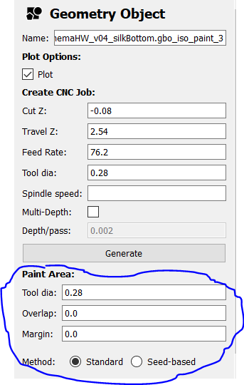
Paint area I set overlap (0.0) and margin (0.0) very low to create small letter, and a tool dia 0.28 to create good profile.
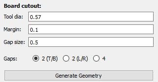
Border put 0.1 to margin, other value is reccomended.
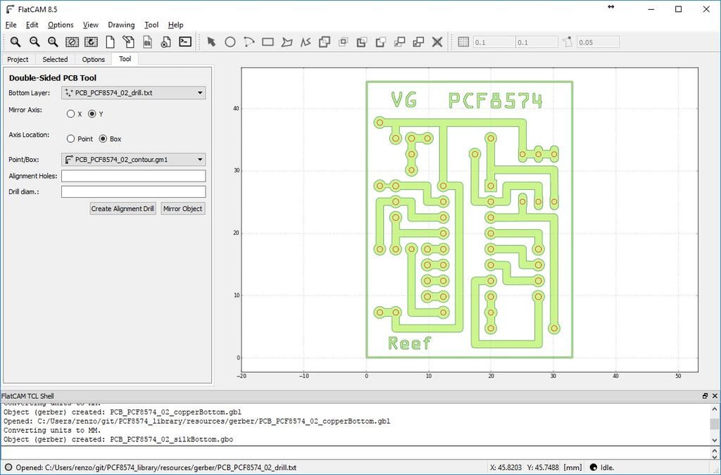
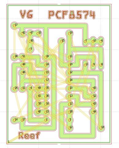
FlatCam: Import File
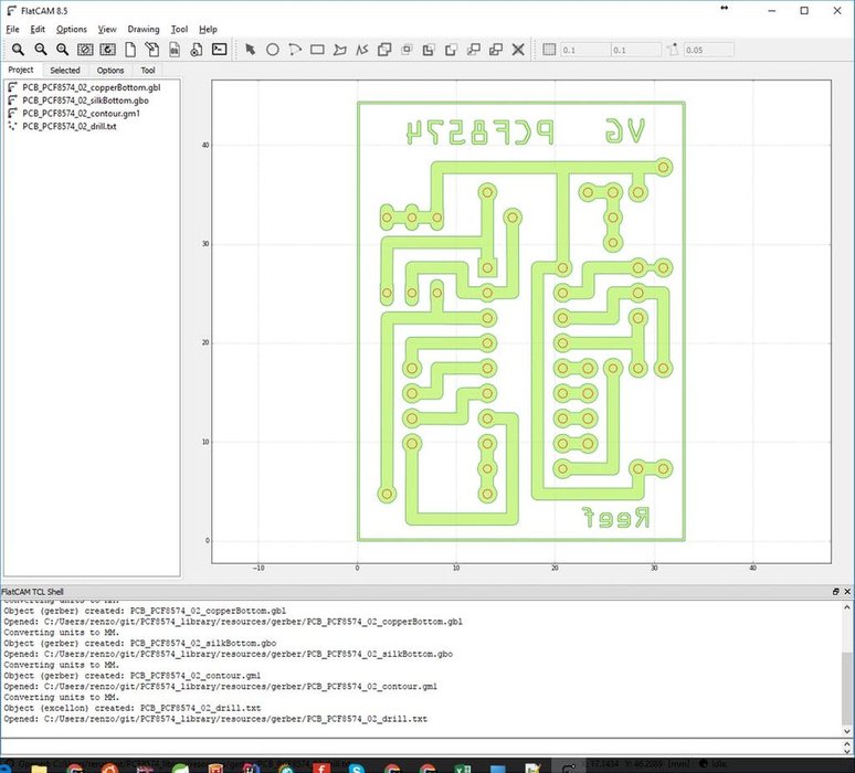
You must import in FlatCam so:
File –> Open Gerber
- copperBottom.gbl
- silkBottom.gbo
- contour.gm1
File –> Open Excellon
- drill.txt
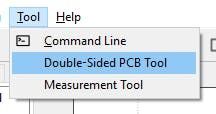
FlatCam: Set Correct Versus
Now we must flip the draw.
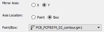
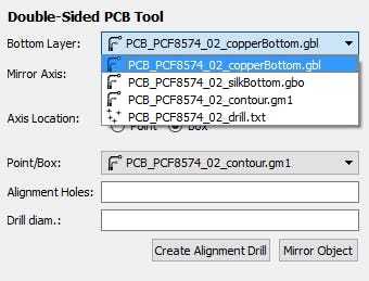
- Open the panel to check the side (Tool –> Double-Sided PCB Tool).
- Set “Mirror Axis” to Y and “Axis location” to Box, and set “Point/Box” to contour.gm1.
- Now select one to one all the Bottom Layer and click to “Mirror Object”, so you flip all layers.
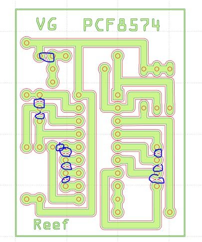
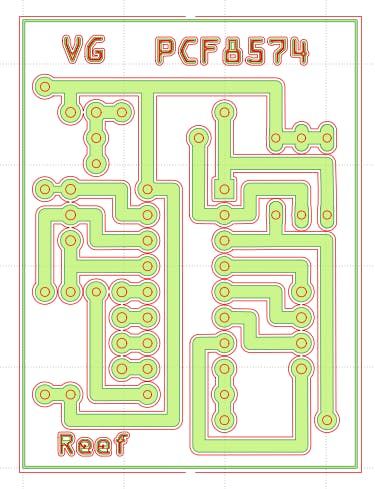
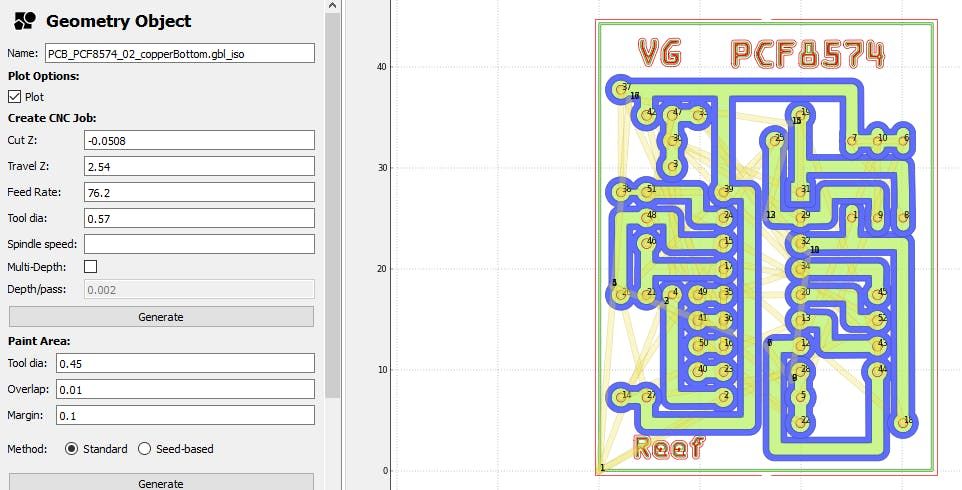
FlatCam: Generate Geometry (copperBottom)
Now double click to select copperBottom and “Generate geometry”.
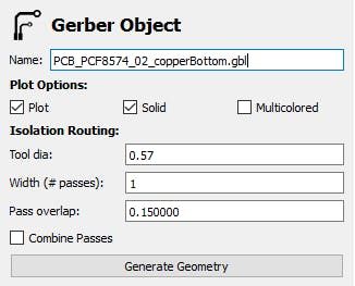
FlatCam draw a red line to the perimeter of copperBottom image, pay attention where the line is not close, at the end of routing you must break that point(if you want to close the line, set the “Tool dia” to a smaller size like 0.50).
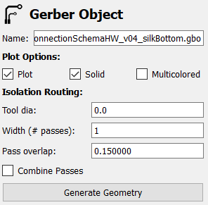
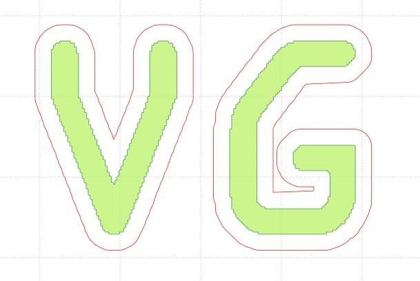
FlatCam: Generate Geometry (silkBottom)
This process is to transform silk bottom in CNC line
For better comprehension sometime is usefully add text:
- Select silkBottom, change tool diameter (like 0.0) to reduce margin. Reducing the margin of “red line” is a simple trick to reduce size of the area, then we can use generated area to cut inside. (In the image I use 0.40 for Tool dia, and a bigger size on Paint Area, but result remain the same)

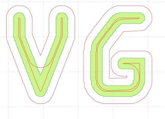
- Then one by one we must create the geometry to milling letter inside by:
- Select silkBottom.gbo_iso than look at “Paint area” panel.
- Reduce “Tool dia”(if needed) to generate a complete geometry inside the letter. Like image 4.
- Do it for all the shapes (or letters) that you want milling.

- Now select all iso paint generated.
- Then Edit –> Join Geometry (create Combo file with all geometry).
FlatCam: Generate Geometry (countour)
Isolated areas
Many people have pointed out to me that I leave the isolated areas, these are harmful because they can generate electromagnetic fields, consequently the small areas to good remove them with the milling, in the case of large areas and well put them all to GND.
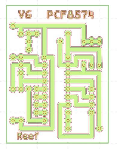
Wide Isolation
You can moltiplicate the passes around the elements with parameter width (# passes).
I put the size of Tool at max possible to have a bigger rings and tracks, I must put a bigger value on pass overlap (like 0.5) to have passes more close so no copper remain in the middle.
Some time I use pass overlap as default and remain a thin copper track in the middle and if a stain do a short I break the copper around to fix It instead remove the stain. But If you don’t find the short there is a rist to create a coil (spira).
It’s better put a pass overlap at 0.5 and add 3 pass to obtain this result.
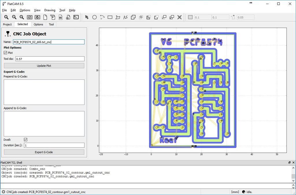
FlatCam: Generate CNC Job (drill)
The last one is drilling but Excellon is already geometry.
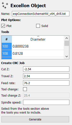
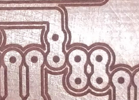
I’ve use the same 0,8mm bit all along and a 1mm bit to enlarge the smallest part.
I also use the punching tool to remove the copper connections that aren’t removed by the CNC.
- Select drill.txt on the screen where there is the list of bit sizes, click and select all (Ctrl+a).
- Then go to generate CNC Job.
- Cut Z is the dept of the hole.
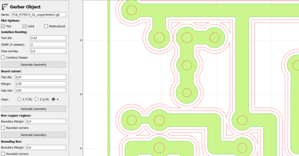
FlatCam: Generate CNC Job (copperBottom)
Tool dia to 0.52 as usual, and set splindle speed if needed (I use dremel with costant speed).
FlatCam: Generate CNC Job (silkBottom)
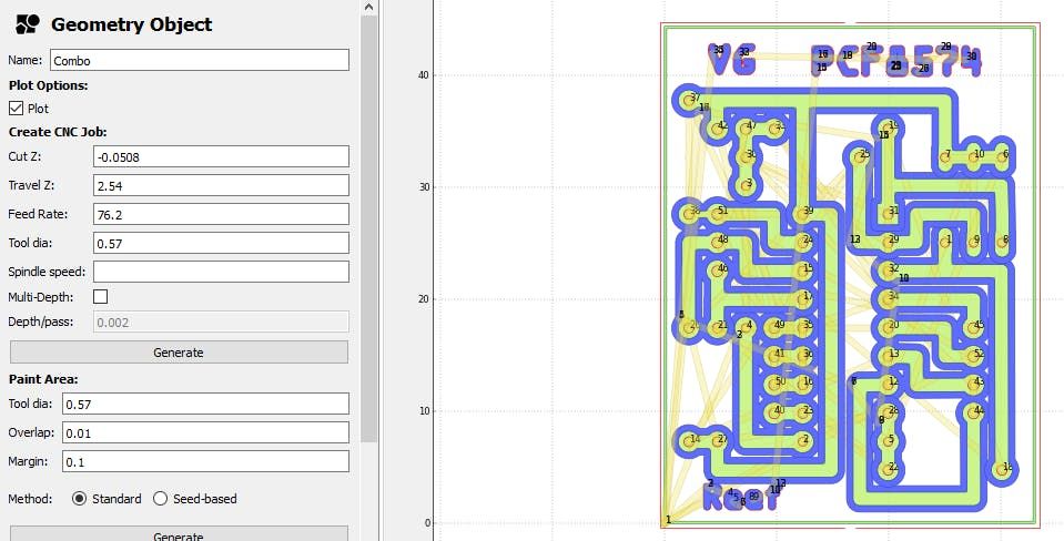
Now select “Combo” element (generated from the joint geometry of silkBottom) then Create CNC Job.
FlatCam: Generate CNC Job (contour)
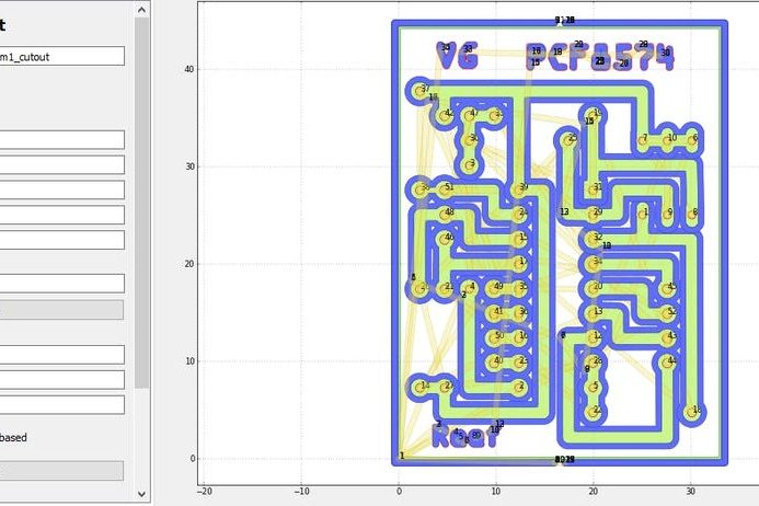
Lastly, select contour.gm1_cutout.
Here I prefer to generate a cut of 0.5mm dept, then I cut to the line with tin scissors, so I set 0.5 of final dept and 0.05 for pass.
FlatCam: Generate Gcode File
From FlatCam select one to one the “*_cnc” file and “Export G-Code”.
Thanks
In the next part we are going to do the work with CNC.