BNO055 for esp32, esp8266, and Arduino: features, configuration, and axes remap – 3
In this article, we are going to explore all features of BON055 and how to configure It.
The BNO055 is a System in Package (SiP), integrating a triaxial 14-bit accelerometer, a triaxial 16-bit gyroscope with a range of ±2000 degrees per second, a triaxial geomagnetic sensor, and a 32-bit cortex M0+ microcontroller running Bosch Sensortec sensor fusion software, in a single package.
Magnetometer features
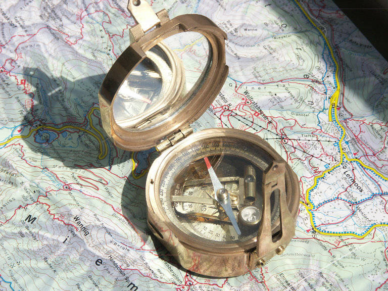
A magnetometer is a device that measures the magnetic field or magnetic dipole moment. Some magnetometers measure the direction, strength, or relative change of a magnetic field at a particular location.
I write some examples and additional information about magnetometers in this article, “GY-291 ADXL345 i2c spi accelerometer with interrupt for esp32, esp8266, stm32 and Arduino“.
- Flexible functionality
Magnetic field range typical ±1300µT (x-, y-axis);
±2500µT (z-axis)
Magnetic field resolution of ~0.3µT- Operating modes:
- Low power
- Regular
- Enhanced regular
- High Accuracy
- Power modes:
- Normal
- Sleep
- Suspend
- Force
- Operating modes:
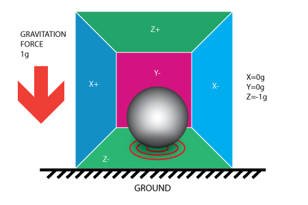
Accelerometer features
An accelerometer is a tool that measures proper acceleration. Proper acceleration is the acceleration (the rate of change of velocity) of a body in its own instantaneous rest frame; this is different from coordinate acceleration, which is acceleration in a fixed coordinate system.
I have explained what it is in detail and written various practical application examples in this article, “GY-291 ADXL345 i2c spi accelerometer with interrupt for esp32, esp8266 and Arduino”.
- Programmable functionality
Acceleration ranges ±2g/±4g/±8g/±16g
Low-pass filter bandwidths 1kHz – <8Hz
Operation modes:- Normal
- Suspend
- Low power
- Standby
- Deep suspend
- On-chip interrupt controller
Motion-triggered interrupt-signal generation for- any-motion (slope) detection
- slow or no motion recognition
- high-g detection
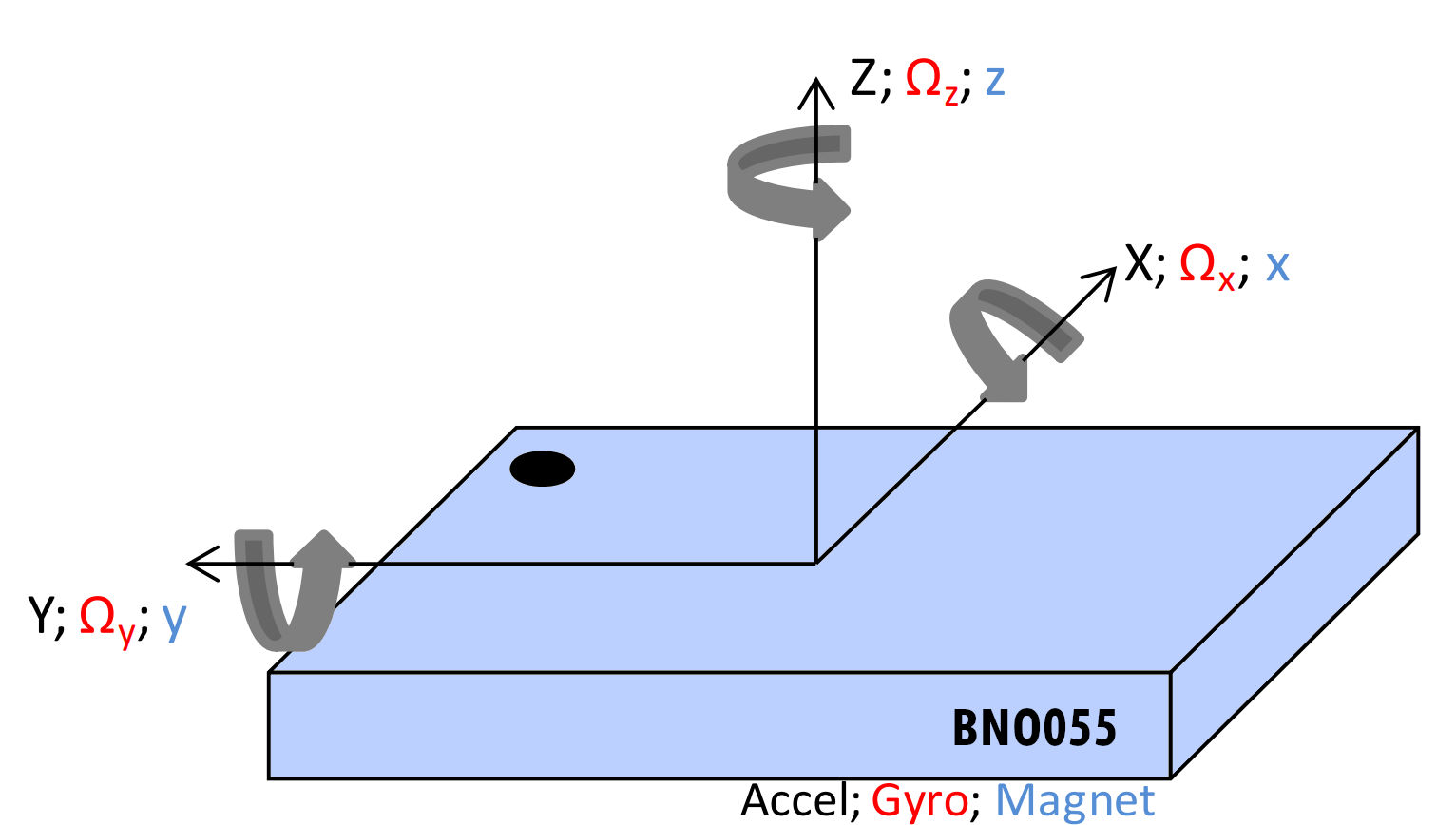
Gyroscope features
A gyroscope is a device used for measuring or maintaining orientation and angular velocity. In origin was a spinning wheel or disc in which the axis of rotation (spin axis) is free to assume any orientation by itself.
- Programmable functionality
Ranges switchable from ±125°/s to ±2000°/s
Low-pass filter bandwidths 523Hz – 12Hz
Operation modes:- Normal
- Fast power up
- Deep suspend
- Suspend
- Advanced power save
- On-chip interrupt controller
Motion-triggered interrupt-signal generation for- any-motion (slope) detection
- high rate
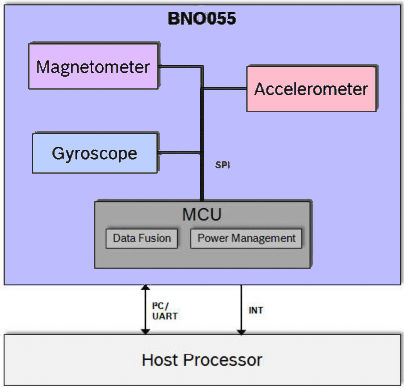
Architecture
I got this image from a datasheet to remember that this sensor had 3 sensors and a microcontroller with fusion software to manage data and give you an absolute position.
Operation modes
The BNO055 provides a variety of output signals, which can be chosen by selecting the appropriate operation mode. The table below lists the different modes and the available sensor signals.
Non-fusion modes (generated only from sensors)
| Operating Mode | Accel | Magn | Gyro | Rel. orient. Fusion | Absol. orient. Fusion |
|---|---|---|---|---|---|
| CONFIGMODE | – | – | – | – | – |
| ACCONLY | X | – | – | – | – |
| MAGONLY | – | X | – | – | – |
| GYROONLY | – | – | X | – | – |
| ACCMAG | X | X | – | – | – |
| ACCGYRO | X | – | X | – | – |
| MAGGYRO | – | X | X | – | – |
| AMG | X | X | X | – | – |
Fusion modes
| Operating Mode | Accel | Magn | Gyro | Rel. orient. Fusion | Absol. orient. Fusion |
|---|---|---|---|---|---|
| IMU | X | – | X | X | – |
| COMPASS | X | X | – | – | X |
| M4G | X | X | X | – | |
| NDOF_FMC_OFF | X | X | X | – | X |
| NDOF | X | X | X | – | X |
So to change the operation mode you only need to call this command:
  //Configuration to NDoF mode
  bno055_set_operation_mode(OPERATION_MODE_NDOF);
The library helps you to map this operations modes with a list of constant
/* Operation mode settings*/
#define OPERATION_MODE_CONFIG			0X00
#define OPERATION_MODE_ACCONLY			0X01
#define OPERATION_MODE_MAGONLY			0X02
#define OPERATION_MODE_GYRONLY			0X03
#define OPERATION_MODE_ACCMAG			0X04
#define OPERATION_MODE_ACCGYRO			0X05
#define OPERATION_MODE_MAGGYRO			0X06
#define OPERATION_MODE_AMG				0X07
#define OPERATION_MODE_IMUPLUS			0X08
#define OPERATION_MODE_COMPASS			0X09
#define OPERATION_MODE_M4G				0X0A
#define OPERATION_MODE_NDOF_FMC_OFF		0X0B
#define OPERATION_MODE_NDOF				0X0C
The default operation mode after power-on is CONFIGMODE.
- Non-Fusion Modes
- ACCONLYIf the application requires only raw accelerometer data, this mode can be chosen. In this mode the other sensors (magnetometer, gyro) are suspended to lower the power consumption. In this mode, the BNO055 behaves like a stand-alone acceleration sensor.
- MAGONLY In MAGONLY mode, the BNO055 behaves like a stand-alone magnetometer, with acceleration sensor and gyroscope being suspended.
- GYROONLY In GYROONLY mode, the BNO055 behaves like a stand-alone gyroscope, with acceleration sensor and magnetometer being suspended.
- ACCMAG Both the accelerometer and magnetometer are switched on, the user can read the data from these two sensors.
- ACCGYRO Both the accelerometer and gyroscope are switched on; the user can read the data from these two sensors.
- MAGGYRO Both the magnetometer and gyroscope are switched on, the user can read the data from these two sensors.
- AMG (ACC-MAG-GYRO) All three sensors accelerometer, magnetometer and gyroscope are switched on.
- ACCONLYIf the application requires only raw accelerometer data, this mode can be chosen. In this mode the other sensors (magnetometer, gyro) are suspended to lower the power consumption. In this mode, the BNO055 behaves like a stand-alone acceleration sensor.
- Fusion modes Sensor fusion modes are meant to calculate measures describing the orientation of the device in space. It can be distinguished between non-absolute or relative orientation and absolute orientation. Absolute orientation means orientation of the sensor with respect to the earth and its magnetic field. In other words, absolute orientation sensor fusion modes calculate the direction of the magnetic north pole.In non-absolute or relative orientation modes, the heading of the sensor can vary depending on how the sensor is placed initially.
All fusion modes provide the heading of the sensor as quaternion data or in Euler angles (roll, pitch and yaw angle). The acceleration sensor is both exposed to the gravity force and to accelerations applied to the sensor due to movement. In fusion modes it is possible to separate the two acceleration sources, and thus the sensor fusion data provides separately linear acceleration (i.e. acceleration that is applied due to movement) and the gravity vector.- IMU (Inertial Measurement Unit)In the IMU mode the relative orientation of the BNO055 in space is calculated from the accelerometer and gyroscope data. The calculation is fast (i.e. high output data rate).
- COMPASS The COMPASS mode is intended to measure the magnetic earth field and calculate the geographic direction.The earth magnetic field is a vector with the horizontal components x,y and the vertical z component. It depends on the position on the globe and natural iron occurrence. For heading calculation (direction of compass pointer) only the horizontal components x and y are used. Therefore the vector components of the earth magnetic field must be transformed in the horizontal plane, which requires the knowledge of the direction of the gravity vector. To summarize, the heading can only be calculated when considering the gravity and magnetic field at the same time.
However, the measurement accuracy depends on the stability of the surrounding magnetic field. Furthermore, since the earth magnetic field is usually much smaller than the magnetic fields that occur around and inside electronic devices, the compass mode requires calibration. - M4G (Magnet for Gyroscope) The M4G mode is similar to the IMU mode, but instead of using the gyroscope signal to detect rotation, the changing orientation of the magnetometer in the magnetic field is used. Since the magnetometer has much lower power consumption than the gyroscope, this mode is less power consuming in comparison to the IMU mode. There are no drift effects in this mode which are inherent to the gyroscope.
However, as for compass mode, the measurement accuracy depends on the stability of the surrounding magnetic field. For this mode no magnetometer calibration is required and also not available. - NDOF_FMC_OFF This fusion mode is same as NDOF mode, but with the Fast Magnetometer Calibration turned ‘OFF’.
- NDOF This is a fusion mode with 9 degrees of freedom where the fused absolute orientation data is calculated from accelerometer, gyroscope and the magnetometer. The advantages of combining all three sensors are a fast calculation, resulting in high output data rate, and high robustness from magnetic field distortions. In this mode the Fast Magnetometer calibration is turned ON and thereby resulting in quick calibration of the magnetometer and higher output data accuracy. The current consumption is slightly higher in comparison to the NDOF_FMC_OFF fusion mode.
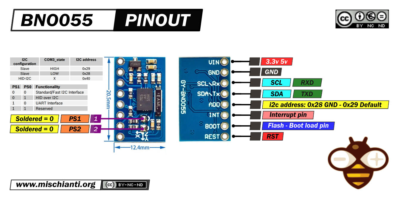
BNO055 pinouts
Exists a lot of module versions of these sensors, I choose the smallest and cheap.
Here the module Aliexpress
All these modules had the same features, but to enable Them, you must do different operations.
This is the clone I use:
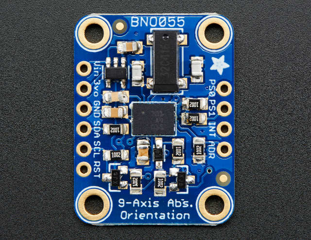
And here is the Adafruit one:
The sensor supports a 3.3v logic level, but the module can be powered by 5v.
Can communicate via i2c (default option) and via UART. To activate the last modality, you must desolder PS1.
| PS1 | PS0 | Functionality |
|---|---|---|
| 0 | 0 | Standard/Fast I2C Interface |
| 0 | 1 | HID over I2C |
| 1 | 0 | UART Interface |
| 1 | 1 | Reserved |
In standard i2c mode, you can select 2 addresses. By default, in this module, the address 0x29 is active. If you put to GND the ADD pin, the address becomes 0x28.
| i2c configuration | ADD | I2C address |
|---|---|---|
| Slave | HIGH | 0x29 |
| Slave | LOW (default) | 0x28 |
| HID-I2C | 0x40 |
INT is configured as an interrupt pin for signaling an interrupt to the host. The interrupt trigger is configured as a raising edge and is latched onto the INT pin. Once an interrupt occurs, the INT pin is set to high and will remain high until it is reset by host.
Axes remap
The device mounting position should not limit the data output of the BNO055 device. The axis of the device can be re-configured to the new reference axis.
In the library, you can manage the axes with this command:
bno055_set_axis_remap_value(REMAP_X_Y);
The possible values are:
/* Axis remap values*/
#define REMAP_X_Y			0X21
#define REMAP_Y_Z			0X18
#define REMAP_Z_X			0X06
#define REMAP_X_Y_Z_TYPE0	0X12
#define REMAP_X_Y_Z_TYPE1	0X09
#define DEFAULT_AXIS		0X24
and the result becomes:
- REMAP_X_Y: This case the axis remapped as Z=Z;X=Y;Y=X
- REMAP_Y_Z: This case the axis remapped as X=X;Y=Z;Z=Y
- REMAP_Z_X: This case the axis remapped as Y=Y;X=Z;Z=X
- REMAP_X_Y_Z_TYPE0: This case the axis remapped as X=Z;Y=X;Z=Y
- REMAP_X_Y_Z_TYPE1: This case the axis remapped as X=Y;Y=Z;Z=X
- DEFAULT_AXIS: This case is the default axis settings X=X;Y=Y;Z=Z
You can also change the sign of che axis with these commands:
	  int change = bno055_set_axis_remap_value(REMAP_X_Y);
	  if (change == SUCCESS) {
		  Serial.println("SUCCESS");
	  }else{
		  Serial.println("FAIL");
	  }
Here is the sketch that, after 10 seconds, remap the X axis with the Y axis and, after 20 seconds, restore the axis.
/**
 * bno055 example remap the X axis to the Y axis
 *
 * by Renzo Mischianti <www.mischianti.org>
 *
 * https://mischianti.org/
 */

#include "BNO055_support.h"		//Contains the bridge code between the API and Arduino
#include <Wire.h>

//The device address is set to BNO055_I2C_ADDR2 in this example. You can change this in the BNO055.h file in the code segment shown below.
// /* bno055 I2C Address */
// #define BNO055_I2C_ADDR1                0x28
// #define BNO055_I2C_ADDR2                0x29
// #define BNO055_I2C_ADDR                 BNO055_I2C_ADDR2

//Pin assignments as tested on the Arduino Due.
//Vdd,Vddio : 3.3V
//GND : GND
//SDA/SCL : SDA/SCL
//PSO/PS1 : GND/GND (I2C mode)

//This structure contains the details of the BNO055 device that is connected. (Updated after initialization)
struct bno055_t myBNO;
struct bno055_euler myEulerData; //Structure to hold the Euler data

unsigned char accelCalibStatus = 0;		//Variable to hold the calibration status of the Accelerometer
unsigned char magCalibStatus = 0;		//Variable to hold the calibration status of the Magnetometer
unsigned char gyroCalibStatus = 0;		//Variable to hold the calibration status of the Gyroscope
unsigned char sysCalibStatus = 0;		//Variable to hold the calibration status of the System (BNO055's MCU)

unsigned long lastTime = 0;

/* Set the delay between fresh samples */
#define BNO055_SAMPLERATE_DELAY_MS (300)

void setup() //This code is executed once
{
  //Initialize I2C communication
  Wire.begin();

  //Initialization of the BNO055
  BNO_Init(&myBNO); //Assigning the structure to hold information about the device

  //Configuration to NDoF mode
  bno055_set_operation_mode(OPERATION_MODE_NDOF);

  delay(1);

  //Initialize the Serial Port to view information on the Serial Monitor
  Serial.begin(115200);
}

bool suspended = false;
bool reactivated = false;

void loop() //This code is looped forever
{
  if ((millis() - lastTime) >= BNO055_SAMPLERATE_DELAY_MS) //To stream at 10Hz without using additional timers
  {
    lastTime = millis();

    bno055_read_euler_hrp(&myEulerData);			//Update Euler data into the structure

    /* The WebSerial 3D Model Viewer expects data as heading, pitch, roll */
    Serial.print(F("Orientation: z "));
    Serial.print((float(myEulerData.h) / 16.00));
    Serial.print(F(", y "));
    Serial.print((float(myEulerData.p) / 16.00));
    Serial.print(F(", x "));
    Serial.print((float(myEulerData.r) / 16.00));
    Serial.println(F(""));
  }
  if (millis() > 10000 && suspended == false) {
	  Serial.print("REMAP X WITH Y! ");

	  int change = bno055_set_axis_remap_value(REMAP_X_Y);
	  if (change == SUCCESS) {
		  Serial.println("SUCCESS");
	  }else{
		  Serial.println("FAIL");
	  }

	  delay(100);
	  suspended = true;
  }

  if (millis() > 20000 && reactivated == false) {
	  Serial.println("RESTORE!");
	  bno055_set_axis_remap_value(DEFAULT_AXIS);

	  reactivated = true;
  }
}
Here is the result where I move in the same direction for the first 10 seconds and after the remap.
Orientation: z 29.50, y 3.00, x 2.69
Orientation: z 29.00, y 3.19, x 2.56
Orientation: z 28.44, y 3.00, x 2.56
Orientation: z 28.25, y 3.00, x 2.62
Orientation: z 28.31, y 3.00, x 2.62
Orientation: z 28.44, y 3.06, x 2.50
Orientation: z 28.25, y 2.94, x -2.94
Orientation: z 26.81, y 2.75, x -25.31
Orientation: z 26.94, y 3.00, x -40.13
Orientation: z 27.56, y 3.25, x -47.06
Orientation: z 28.50, y 3.56, x -49.56
Orientation: z 28.56, y 3.75, x -50.88
Orientation: z 28.69, y 3.87, x -50.75
Orientation: z 29.50, y 3.19, x -29.56
Orientation: z 28.75, y 2.87, x -9.25
Orientation: z 28.06, y 3.25, x -1.62
Orientation: z 28.06, y 3.37, x 2.69
Orientation: z 28.19, y 3.50, x 2.94
Orientation: z 28.19, y 3.44, x 2.94
Orientation: z 28.19, y 3.44, x 2.94
Orientation: z 28.12, y 3.44, x 3.00
Orientation: z 28.12, y 3.44, x 3.00
Orientation: z 28.12, y 3.44, x 3.00
Orientation: z 28.12, y 3.44, x 3.00
Orientation: z 28.12, y 3.44, x 3.00
Orientation: z 28.12, y 3.44, x 3.00
Orientation: z 28.12, y 3.44, x 3.00
Orientation: z 28.12, y 3.44, x 3.00
Orientation: z 28.12, y 3.44, x 3.00
Orientation: z 28.12, y 3.44, x 3.00
Orientation: z 28.12, y 3.44, x 3.00
Orientation: z 28.12, y 3.44, x 3.00
Orientation: z 28.12, y 3.44, x 3.00
REMAP X WITH Y! SUCCESS
Orientation: z 28.12, y 2.19, x 1.81
Orientation: z 28.12, y -1.31, x -0.88
Orientation: z 27.25, y -10.94, x -1.50
Orientation: z 27.19, y -17.62, x -1.50
Orientation: z 27.62, y -18.12, x -1.87
Orientation: z 28.44, y 5.12, x -3.06
Orientation: z 29.12, y 22.75, x -3.50
Orientation: z 29.44, y 32.81, x -3.56
Orientation: z 29.56, y 35.63, x -3.56
Orientation: z 29.69, y 37.88, x -3.56
Orientation: z 29.87, y 38.88, x -3.50
Orientation: z 30.19, y 41.56, x -3.44
Orientation: z 31.31, y 72.44, x -2.87
Orientation: z 30.31, y 77.00, x -3.00
Orientation: z 28.62, y 35.81, x -4.06
Orientation: z 27.94, y 13.50, x -3.81
Orientation: z 27.62, y 3.56, x -3.50
Orientation: z 27.50, y 0.00, x -3.37
Orientation: z 27.50, y -1.12, x -3.31
Orientation: z 27.50, y -1.69, x -3.31
Orientation: z 27.44, y -1.94, x -3.25
Orientation: z 27.44, y -2.12, x -3.25
Orientation: z 27.44, y -2.31, x -3.25
Orientation: z 27.44, y -2.37, x -3.25
Orientation: z 27.44, y -2.37, x -3.25
Orientation: z 27.37, y -2.37, x -3.37
Orientation: z 27.37, y -2.62, x -3.62
Orientation: z 27.37, y -2.69, x -3.50
Orientation: z 27.37, y -2.69, x -3.37
Orientation: z 27.37, y -2.69, x -3.31
Orientation: z 27.37, y -2.69, x -3.25
Orientation: z 27.37, y -2.69, x -3.25
Orientation: z 27.37, y -2.69, x -3.25
RESTORE!
Orientation: z 0.00, y 0.00, x 0.00
Orientation: z 27.37, y 0.13, x 0.00
Orientation: z 27.37, y 1.12, x 1.12
Orientation: z 27.37, y 1.56, x 1.56
Orientation: z 27.37, y 1.75, x 1.87
Orientation: z 27.37, y 1.94, x 2.00
Orientation: z 27.37, y 2.00, x 2.12
Orientation: z 27.37, y 2.12, x 2.19
Orientation: z 27.37, y 2.12, x 2.25
Orientation: z 27.37, y 2.12, x 2.25
Orientation: z 27.37, y 2.12, x 2.25
Sensor configuration
The fusion outputs of the BNO055 are tightly linked with the sensor configuration settings. Due to this fact, the sensor configuration is limited when BNO055 is configured to run in any of the fusion operating modes.
Accelerometer
Default parameters
| Parameters | Value |
|---|---|
| Power Mode | NORMAL |
| Range | +/- 4g |
| Bandwidth | 62.5Hz |
| Resolution | 14 bits |
You can change these parameters with these commands.
Acceleration range
bno055_set_accel_range(ACCEL_RANGE_4G);
Here the constant defined in the library.
/* Accel Range */
#define ACCEL_RANGE_2G		0X00
#define ACCEL_RANGE_4G		0X01
#define ACCEL_RANGE_8G		0X02
#define ACCEL_RANGE_16G		0X03
Acceleration bandwidth
bno055_set_accel_bandwidth(ACCEL_BW_62_5Hz);
Here are the constants defined in the library.
/* Accel Bandwidth*/
#define ACCEL_BW_7_81Hz		0x00
#define ACCEL_BW_15_63Hz	0x01
#define ACCEL_BW_31_25Hz	0x02
#define ACCEL_BW_62_5Hz		0X03
#define ACCEL_BW_125Hz		0X04
#define ACCEL_BW_250Hz		0X05
#define ACCEL_BW_500Hz		0X06
#define ACCEL_BW_1000Hz		0X07
Acceleration power mode
bno055_set_accel_powermode(ACCEL_NORMAL);
Here are the constants defined in the library.
/* Accel Power mode*/
#define ACCEL_NORMAL			0X00
#define ACCEL_SUSPEND			0X01
#define ACCEL_LOWPOWER_1		0X02
#define ACCEL_STANDBY			0X03
#define ACCEL_LOWPOWER_2		0X04
#define ACCEL_DEEPSUSPEND		0X05
The accelerometer sensor operation mode is not configurable by the user when BNO power mode is configured as low power mode. BNO rewrites the user-configured value to Normal mode when switching from config mode to any BNO operation mode. This is used to achieve the BNO low power mode performance.
Gyroscope
Default parameters
| Parameters | Value |
|---|---|
| Power Mode | NORMAL |
| Range | 2000 °/s |
| Bandwidth | 32Hz |
| Resolution | 16 bits |
You can change these parameters with this command.
Gyroscope range
bno055_set_gyro_range(GYRO_RANGE_2000rps);
Here are the constants defined in the library.
/* Gyro range*/
#define GYRO_RANGE_2000rps		0x00
#define GYRO_RANGE_1000rps		0x01
#define GYRO_RANGE_500rps		0x02
#define GYRO_RANGE_250rps		0x03
#define GYRO_RANGE_125rps		0x04
Gyroscope bandwidth
bno055_set_gyro_bandwidth(GYRO_BW_32Hz);
Here are the constants defined in the library.
/* Gyro Bandwidth*/
#define GYRO_BW_523Hz		0x00
#define GYRO_BW_230Hz		0x01
#define GYRO_BW_116Hz		0x02
#define GYRO_BW_47Hz		0x03
#define GYRO_BW_23Hz		0x04
#define GYRO_BW_12Hz		0x05
#define GYRO_BW_64Hz		0x06
#define GYRO_BW_32Hz		0x07
Gyroscope operation mode
bno055_set_gyro_operation_mode(GYRO_OPR_MODE_NORMAL);
Here the constant is defined in the library.
/* Gyro Operation mode*/
#define GYRO_OPR_MODE_NORMAL				0X00
#define GYRO_OPR_MODE_FASTPOWERUP			0X01
#define GYRO_OPR_MODE_DEEPSUSPEND			0X02
#define GYRO_OPR_MODE_SUSPEND				0X03
#define GYRO_OPR_MODE_ADVANCE_POWERSAVE		0X04
Magnetometer
Default parameters
| Parameters | Value |
|---|---|
| Power Mode | FORCED |
| ODR | 20Hz |
| XY Repetition | 15 |
| Z Repetition | 16 |
| Resolution x/y/z | 13/13/15 bits |
Magnetometer output data rate
bno055_set_mag_data_outrate(MAG_DATA_OUTRATE_20Hz);
Here are the constants defined in the library.
/* Mag data output rate*/
#define MAG_DATA_OUTRATE_2Hz		0X00
#define MAG_DATA_OUTRATE_6Hz		0X01
#define MAG_DATA_OUTRATE_8Hz		0X02
#define MAG_DATA_OUTRATE_10Hz		0X03
#define MAG_DATA_OUTRATE_15Hz		0X04
#define MAG_DATA_OUTRATE_20Hz		0X05
#define MAG_DATA_OUTRATE_25Hz		0X06
#define MAG_DATA_OUTRATE_30Hz		0X07
Magnetometer operation mode
bno055_set_mag_operation_mode(MAG_OPR_MODE_REGULAR);
Here are the constants defined in the library.
/* Mag Operation mode*/
#define MAG_OPR_MODE_LOWPOWER				0X00
#define MAG_OPR_MODE_REGULAR				0X01
#define MAG_OPR_MODE_ENHANCED_REGULAR		0X02
#define MAG_OPR_MODE_HIGH_ACCURACY			0X03
Magnetometer power mode
bno055_set_mag_powermode(MAG_POWER_MODE_NORMAL);
Here are the constants defined in the library.
/* Mag power mode*/
#define MAG_POWER_MODE_NORMAL					0X00
#define MAG_POWER_MODE_SLEEP					0X01
#define MAG_POWER_MODE_SUSPEND					0X02
#define MAG_POWER_MODE_FORCE_MODE				0X03
Thanks
- BNO055 accelerometer, gyroscope, magnetometer with basic Adafruit library
- BNO055 for esp32, esp8266, and Arduino: wiring and advanced Bosch library
- BNO055 for esp32, esp8266, and Arduino: features, configuration, and axes remap
- BNO055: power modes, accelerometer, and motion interrupt
- BNO055 for esp32, esp8266, and Arduino: enable INT pin and accelerometer High G Interrupt
- BNO055 for esp32, esp8266, and Arduino: Gyroscope High Rate and Any Motion Interrupt