STM32F4 Black-pill: WiFi shield (WiFiNINA)
First of all, read the article “STM32: WiFiNINA with ESP32 WiFi Co-Processor“, where there are all the basics to understand this shield usage better.
For me, It’s very important the network connection and network limitation on STM32 It’s very tedious. Adafruit offers a solution, but I think that a shield It’s more usable.
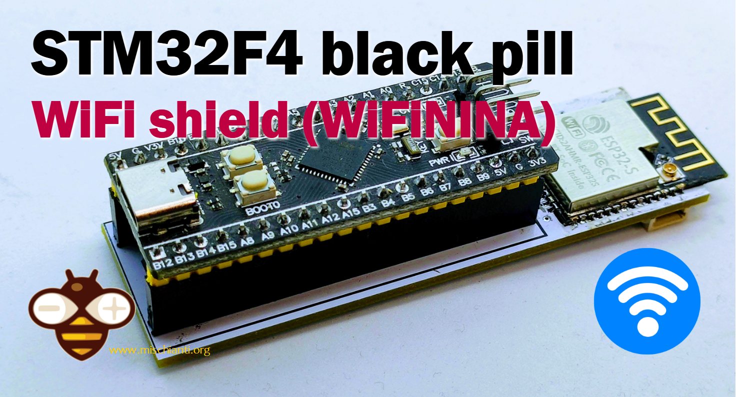
So I design a shield to add WiFi to my STM32F4 black-pill.
PCB
You can get the PCB for a few dollars.
STM32F4 WiFi Shield PCB PCBWay

The PCB is quite simple, and I also add an interface to update the firmware over esp32. Strangely, esp32-s seems to update better than esp32-wroom-32. Probably the thin wire adds noise to the serial transfer.
Here my selection of esp32 ESP32 Dev Kit v1 - TTGO T-Display 1.14 ESP32 - NodeMCU V3 V2 ESP8266 Lolin32 - NodeMCU ESP-32S - WeMos Lolin32 - WeMos Lolin32 mini - ESP32-CAM programmer - ESP32-CAM bundle - ESP32-WROOM-32 - ESP32-S
WeAct devices are of good quality and you shouldn’t get any surprises.
Here my selection of stm32 STM32F103C8T6 STM32F401 STM32F411 ST-Link v2 ST-Link v2 official
Here is the PCB drawing.
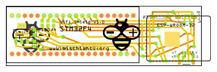
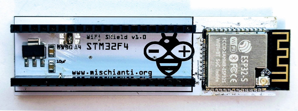
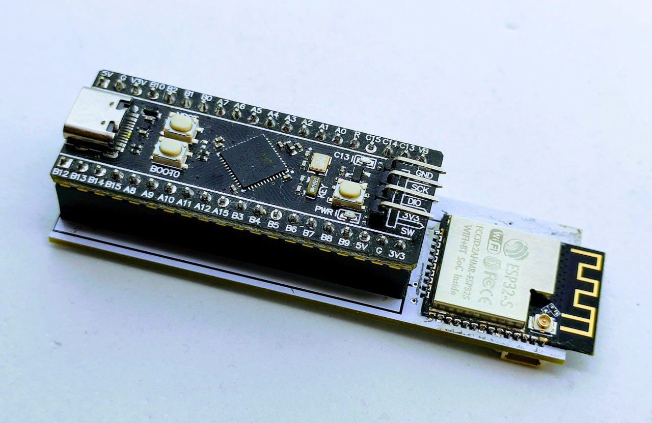
The result is this PCB. Here is the top view:
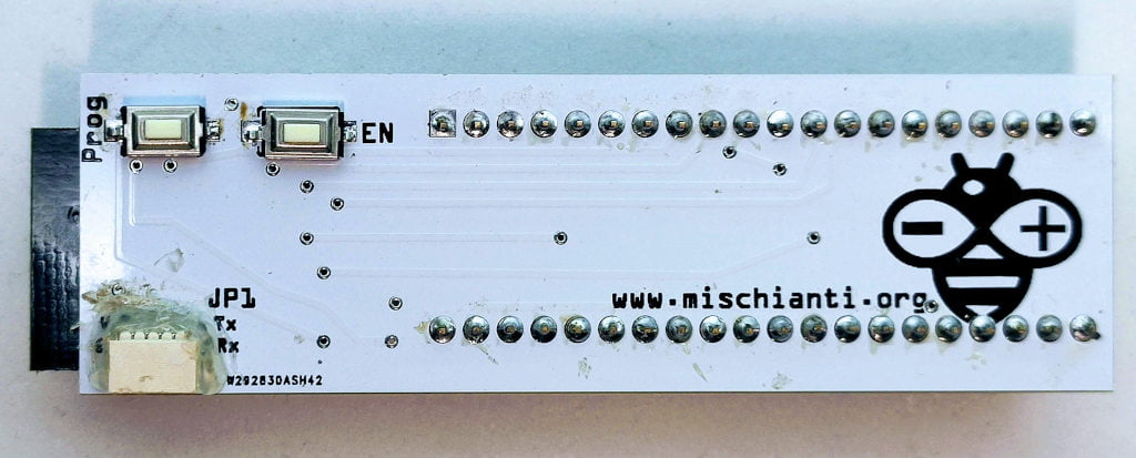
and here is the bottom.
At the top, you can see the pad to solder to select the CS pin of the WiFi module (refer to the article about Wifi coprocessor).
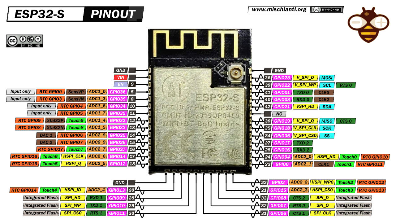
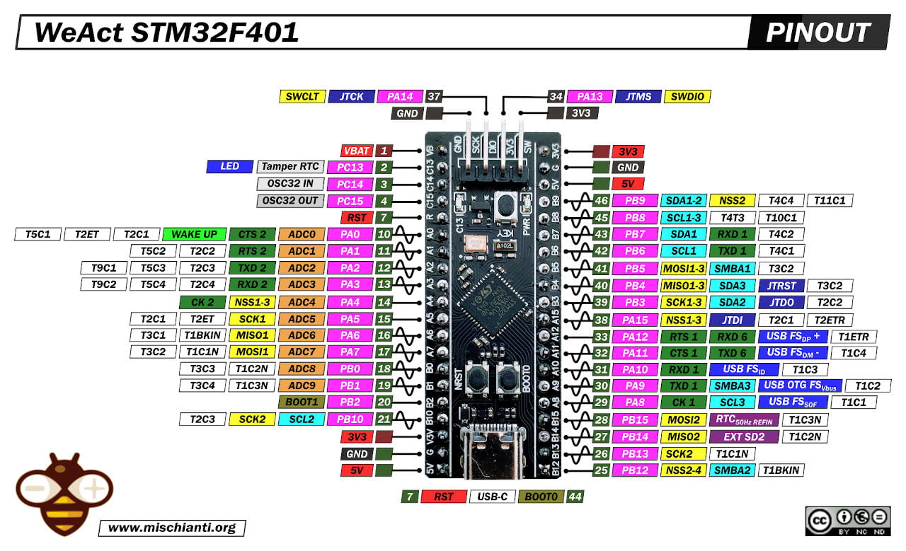
| ESP32 | Description | STM32 |
|---|---|---|
| GPIO05 | CS | PB1, PB0, PA4 |
| GPIO18 | SCK | PA5 |
| GPIO23 | MISO | PA6 |
| GPIO14 | MOSI | PA7 |
| GPIO33 | BUSY/READY (IRQ) | PA3 |
| EN (reset on LOW) | RST/EN | PA2 |
| GPIO0 (Flash) | Flash | PA1 (not needed) |
| GND | GND | GND |
| VIN | 3.3v | From 5v to a voltage regulator |
At the bottom, I add a terminal SH1.0 horizontal to interface with FTDI and two buttons to program and reset the esp32.
Here a set of terminal Terminal sh1.0 jst1.25 zh1.5 ph2.0 xh2.54 - 2.54mm PCB Screw Terminal Blocks
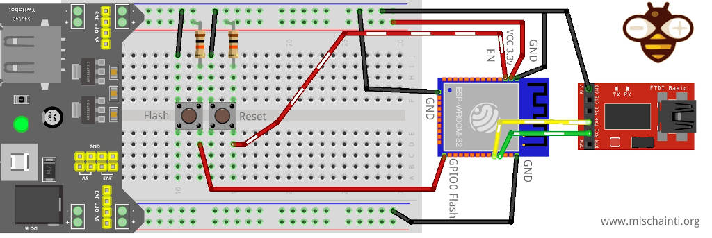
You can refer to the article “ESP32-wroom-32, esp32-S: flash, pinout, specs and IDE configuration” which explains how to program esp32 without a prototyping board.
Assembling the PCB
The board is very simple to assemble. You need:
- an esp32-s or an esp32-wroom-32
The WiFi co-processor ESP32 Dev Kit v1 - TTGO T-Display 1.14 ESP32 - NodeMCU V3 V2 ESP8266 Lolin32 - NodeMCU ESP-32S - WeMos Lolin32 - WeMos Lolin32 mini - ESP32-CAM programmer - ESP32-CAM bundle - ESP32-WROOM-32 - ESP32-S
- SMD voltage regulator AMS1117-3.3V
Voltage regulator AliExpress SMD (AMS1117) - AliExpress 3.3v (LM1117) - AliExpress 5v (7805) - AliExpress 9v (7809)AliExpress 12v (7812) - AliExpress 3.3v TO-92 (78L33)
- SMD buttons
SMD buttons SMD buttons 3X6X2.5
- SH1.0 terminal
Terminal Terminal sh1.0 jst1.25 zh1.5 ph2.0 xh2.54 - 2.54mm PCB Screw Terminal Blocks
- 805 SMD resistor (10uF)
- Female header
Before assembling upload the firmware to the esp32, the little SMD connector can generate some noise, and some esp32-wroom-32 doesn’t allow uploading the firmware.
Before assembling upload the WiFi firmware to the esp32
You also need to solder the relative pad to the CS pin you select.
Use the connector to upload the firmware to the esp32
You can refer to this article “ESP32-wroom-32, esp32-S: flash, pinout, specs and IDE configuration” to have full information about the process.
As I already said, I added a connector to upload the firmware to the esp32. To use It, you need an FTDI.
FTDI USB to TTL CH340G - USB to TTL FT232RL
You also need to crimp a cable, and you can see the pin position on the PCB (G, V, Tx, and Rx).
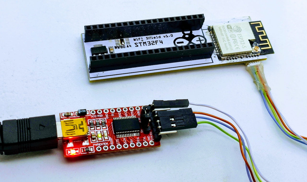
The upload process is simple:
- Connect the FTDI;
- Hold down Prog button;
- Click and release EN button;
- Release Prog button (now esp32 is in download mode);
- Launch the upload process on the port of your FTDI.
You can find the complete process and firmware in the relative article “STM32: WiFiNINA with ESP32 WiFi Co-Processor“.
First communication test
Now put your STM32F4 on your shield.
And we will test basic communication between your ESP32 and your STM32.
Check firmware sketch
First of all, the sketch asks for the version of the firmware installed on the ESP32.
/*
 * This example check if the firmware loaded on the NINA module
 * is updated.
 *
 * modified by Renzo Mischianti <www.mischianti.org>
 *
 * www.mischianti.org
 *
 */
#include <SPI.h>
#include <WiFiNINA.h>

#define SPIWIFI       SPI  // The SPI port
#define SPIWIFI_SS    PA4   // Chip select pin
#define ESP32_RESETN  PA2   // Reset pin
#define SPIWIFI_ACK   PA3   // a.k.a BUSY or READY pin
#define ESP32_GPIO0   -1

void setup() {
  // Initialize serial
  Serial.begin(9600);
  while (!Serial) {
    ; // wait for serial port to connect. Needed for native USB port only
  }

  // Print a welcome message
  Serial.println("WiFiNINA firmware check.");
  Serial.println();

  // Set up the pins!
  WiFi.setPins(SPIWIFI_SS, SPIWIFI_ACK, ESP32_RESETN, ESP32_GPIO0, &SPIWIFI);

  // check for the WiFi module:
  if (WiFi.status() == WL_NO_MODULE) {
    Serial.println("Communication with WiFi module failed!");
    // don't continue
    while (true);
  }

  // Print firmware version on the module
  String fv = WiFi.firmwareVersion();
  String latestFv;
  Serial.print("Firmware version installed: ");
  Serial.println(fv);

  latestFv = WIFI_FIRMWARE_LATEST_VERSION;

  // Print required firmware version
  Serial.print("Latest firmware version available : ");
  Serial.println(latestFv);

  // Check if the latest version is installed
  Serial.println();
  if (fv >= latestFv) {
    Serial.println("Check result: PASSED");
  } else {
    Serial.println("Check result: NOT PASSED");
    Serial.println(" - The firmware version on the module do not match the");
    Serial.println("   version required by the library, you may experience");
    Serial.println("   issues or failures.");
  }
}

void loop() {
  // do nothing
}
Remember to select the correct CS pin (according to your pad soldering)
#define SPIWIFI_SS PB0 // Chip select pin
If all is ok, the output of the sketch is:
Firmware version installed: 1.7.4
Latest firmware version available : 1.2.1

Check result: PASSED
This is good, but the test is insufficient to ensure that all works correctly. Now, we upload a sketch to scan all wifi networks.
WiFi networks scanner sketch
/*

 This example  prints the board's MAC address, and
 scans for available Wifi networks using the NINA module.
 Every ten seconds, it scans again. It doesn't actually
 connect to any network, so no encryption scheme is specified.

 Circuit:
 * Board with NINA firmware on it (In this case its an Adafruit AirLift)

 created 13 July 2010
 by dlf (Metodo2 srl)
 modified 21 Junn 2012
 by Tom Igoe and Jaymes Dec
 modified 17 May 2022
 by Renzo Mischianti

 */


#include <SPI.h>
#include <WiFiNINA.h>

#define SPIWIFI       SPI  // The SPI port
#define SPIWIFI_SS    PA4   // Chip select pin
#define ESP32_RESETN  PA2   // Reset pin
#define SPIWIFI_ACK   PA3   // a.k.a BUSY or READY pin
#define ESP32_GPIO0   -1

void printMacAddress(byte mac[]);
void printEncryptionType(int thisType);
void listNetworks();

void setup() {
  //Initialize serial and wait for port to open:
  Serial.begin(9600);
  while (!Serial) {
    ; // wait for serial port to connect. Needed for native USB port only
  }

  Serial.println("WiFi Scanning test");

  // Set up the pins!
  WiFi.setPins(SPIWIFI_SS, SPIWIFI_ACK, ESP32_RESETN, ESP32_GPIO0, &SPIWIFI);

  // check for the WiFi module:
  while (WiFi.status() == WL_NO_MODULE) {
    Serial.println("Communication with WiFi module failed!");
    // don't continue
    delay(10000);
  }
  String fv = WiFi.firmwareVersion();
  Serial.println(fv);
  if (fv < "1.0.0") {
    Serial.println("Please upgrade the firmware");
    while (1) delay(10);
  }
  Serial.println("Firmware OK");

  // print your MAC address:
  byte mac[6];
  WiFi.macAddress(mac);
  Serial.print("MAC: ");
  printMacAddress(mac);
}

void loop() {
  // scan for existing networks:
  Serial.println("Scanning available networks...");
  listNetworks();
  delay(10000);
}

void listNetworks() {
  // scan for nearby networks:
  Serial.println("** Scan Networks **");
  int numSsid = WiFi.scanNetworks();
  if (numSsid == -1) {
    Serial.println("Couldn't get a wifi connection");
    while (true);
  }

  // print the list of networks seen:
  Serial.print("number of available networks:");
  Serial.println(numSsid);

  // print the network number and name for each network found:
  for (int thisNet = 0; thisNet < numSsid; thisNet++) {
    Serial.print(thisNet);
    Serial.print(") ");
    Serial.print(WiFi.SSID(thisNet));
    Serial.print("\tSignal: ");
    Serial.print(WiFi.RSSI(thisNet));
    Serial.print(" dBm");
    Serial.print("\tEncryption: ");
    printEncryptionType(WiFi.encryptionType(thisNet));
  }
}

void printEncryptionType(int thisType) {
  // read the encryption type and print out the name:
  switch (thisType) {
    case ENC_TYPE_WEP:
      Serial.println("WEP");
      break;
    case ENC_TYPE_TKIP:
      Serial.println("WPA");
      break;
    case ENC_TYPE_CCMP:
      Serial.println("WPA2");
      break;
    case ENC_TYPE_NONE:
      Serial.println("None");
      break;
    case ENC_TYPE_AUTO:
      Serial.println("Auto");
      break;
    case ENC_TYPE_UNKNOWN:
    default:
      Serial.println("Unknown");
      break;
  }
}


void printMacAddress(byte mac[]) {
  for (int i = 5; i >= 0; i--) {
    if (mac[i] < 16) {
      Serial.print("0");
    }
    Serial.print(mac[i], HEX);
    if (i > 0) {
      Serial.print(":");
    }
  }
  Serial.println();
}
If you obtain an output like this, the board is ok.
Scanning available networks...
** Scan Networks **
number of available networks:6
0) reef-casa-sopra	Signal: -49 dBm	Encryption: WPA2
1) reef-casa-orto	Signal: -69 dBm	Encryption: WPA2
2) reef-casa-centro	Signal: -78 dBm	Encryption: WPA2
3) reef-casa-centro	Signal: -83 dBm	Encryption: WPA2
4) reef-casa-sotto	Signal: -87 dBm	Encryption: WPA2
5) TIM-18355607	Signal: -91 dBm	Encryption: WPA2
Thanks
- STM32F1 Blue-Pill: pinout, specs, and Arduino IDE configuration (STM32duino and STMicroelectronics)
- STM32: program (STM32F1) via USB with STM32duino bootloader
- STM32: programming (STM32F1 STM32F4) via USB with HID boot-loader
- STM32F4 Black-Pill: pinout, specs, and Arduino IDE configuration
- STM32: ethernet w5500 with plain HTTP and SSL (HTTPS)
- STM32: ethernet enc28j60 with plain HTTP and SSL (HTTPS)
- STM32: WiFiNINA with ESP32 WiFi Co-Processor
- How to use SD card with stm32 and SdFat library
- \STM32: SPI flash memory FAT FS
- STM32: internal RTC, clock, and battery backup (VBAT)
- STM32 LoRa
- STM32 Power saving
- STM32F1 Blue-Pill clock and frequency management
- STM32F4 Black-Pill clock and frequency management
- Intro and Arduino vs STM framework
- Library LowPower, wiring, and Idle (STM Sleep) mode
- Sleep, deep sleep, shutdown, and power consumption
- Wake up from RTC alarm and Serial
- Wake up from the external source
- Backup domain intro and variable preservation across reset
- RTC backup register and SRAM preservation
- STM32 send emails with attachments and SSL (like Gmail): w5500, enc28j60, SD, and SPI Fash