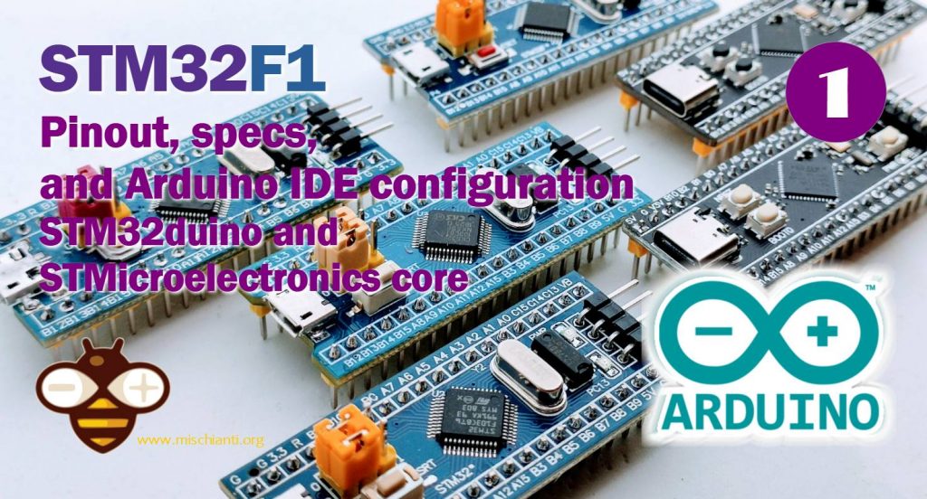
STM32F1: pinout, specs, and Arduino IDE configuration (STM32duino and STMicroelectronics) – 1
SMT32 details
The STM32 family of 32-bit microcontrollers is based on the Arm® Cortex®-M processor.
These products combine very high performance, real-time capabilities digital signal processing, low-power / low-voltage operation, and connectivity while maintaining full integration and ease of development.
The STM32 microcontrollers, based on an industry-standard core, come with a vast choice of tools and software to support project development, making this family of products ideal for both small projects and end-to-end platforms.
Here the most commons STM32 STM32F103C8T6 STM32F401 STM32F411 ST-Link v2 ST-Link v2 official
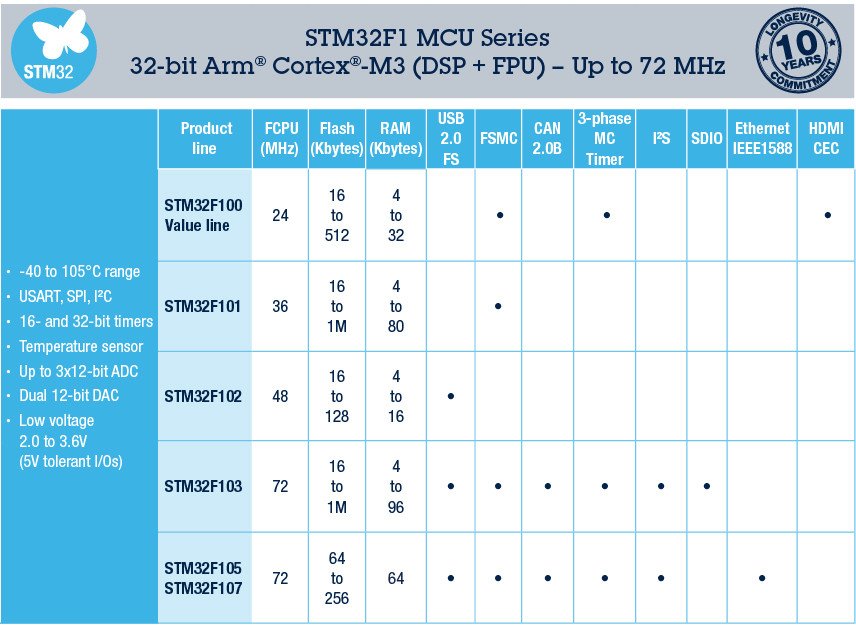
Specs
There is a wide variety of stm32; here is a schematization of the main category.

A more detailed classification can do with the part number decoding:
STM32F051R8
STM32xxwwyz
- xx – Family
- ww – subtype: differs in equipment of peripherals and this depend on certain family
- y – Package pin count
- z – FLASH memory size
Family: [xx]
| Code | Core | Max freq [MHz] | Max FLASH [KB] | Max SRAM [KB] | Target |
|---|---|---|---|---|---|
| F0 | Cortex-M0 | 48 | 256 | 32 | Mainstream |
| F1 | Cortex-M3 | 72 | 1024 | 96 | Mainstream |
| F2 | Cortex-M3 | 120 | 1024 | 128 | High performance |
| F3 | Cortex-M4F | 72 | 512 | 80 | Mainstream |
| F4 | Cortex-M4F | 180 | 2048 | 384 | High performance |
| G0 | Cortex-M0+ | 64 | 128 | 36 | Mainstream |
| G4 | Cortex-M4F | 170 | 512 | 128 | Mainstream |
| F7 | Cortex-M7F | 216 | 2048 | 512 | High performance |
| H7 | Cortex-M7F | 480 | 2048 | 1024 | High performance |
| WB | Cortex-M4F | 64 | 1024 | 256 | Wireless |
| WL | Cortex-M4 | 48 | 256 | 64 | Wireless |
| L0 | Cortex-M0+ | 32 | 192 | 20 | Ultra-low-power |
| L1 | Cortex-M3 | 32 | 512 | 80 | Ultra-low-power |
| L4 | Cortex-M4F | 80 | 1024 | 320 | Ultra-low-power |
| L4+ | Cortex-M4F | 120 | 2048 | 640 | Ultra-low-power |
| L5 | Cortex-M33F | 110 | 512 | 256 | Ultra-low-power |
| U5 | Cortex-M33F | 160 | 2048 | 786 | Ultra-low-power |
Package pin count [y]
| Code | Number of pins |
|---|---|
| A | 169 |
| B | 208 |
| C | 48 |
| F | 20 |
| G | 28 |
| H | 40 |
| I | 176 |
| J | 8/72 |
| K | 32 |
| M | 81 |
| N | 216 |
| Q | 132 |
| R | 64 |
| T | 36 |
| U | 63 |
| V | 100 |
| Z | 144 |
FLASH memory size [z]
| Code | FLASH size [KB] |
|---|---|
| 4 | 16 |
| 6 | 32 |
| 8 | 64 |
| B | 128 |
| Z | 192 |
| C | 256 |
| D | 384 |
| E | 512 |
| F | 768 |
| G | 1024 |
| H | 1536 |
| I | 2048 |
STM32F1 details
ST’s STM32F1 Series of mainstream MCUs covers the needs of a large variety of applications, the Arm® Cortex™-M microcontrollers give a good performance with first-class peripherals and low-power, low-voltage operation is paired with a high level of integration at accessible prices with a simple architecture and easy-to-use tools.
Pinouts
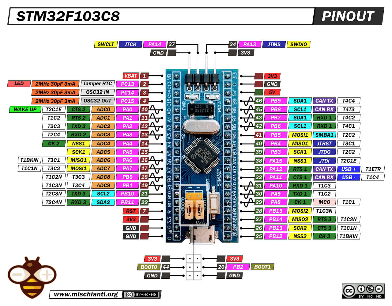
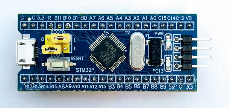
STM32F103C8T6 Blue Pill: high resolution pinout and specs
STM32F103C6T6 Blue Pill: high-resolution pinout and specs
The significant advantage of these devices is that the pins have 3.3v logic, but some are 5v tolerant; you can see them in the pinout diagram (green square 5v tolerant, red square only 3.3v).
Wiring
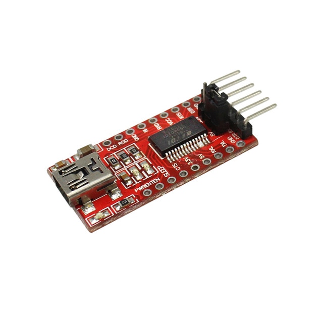
The device you had to buy probably arrived without a bootloader, and you need an FTDI programmer. I usually use a basic model, but in this case, It’s more simple to use a module with integrated power output.
It exists more expensive FT232RL or FT232 module, but a CH340G or CH340 working very well.
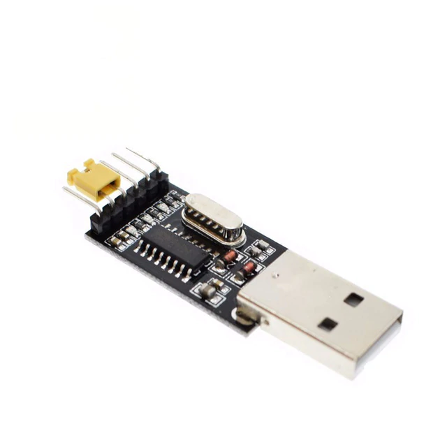
Here the two model USB to TTL CH340G - USB to TTL FT232RL
Connection schema with FTDI (USBtoTTL)
First of all, we will upload a sketch in an empty stm32 blue pill, in my case STM32F103C8T6. to do that, we must use the FTDI in this manner.
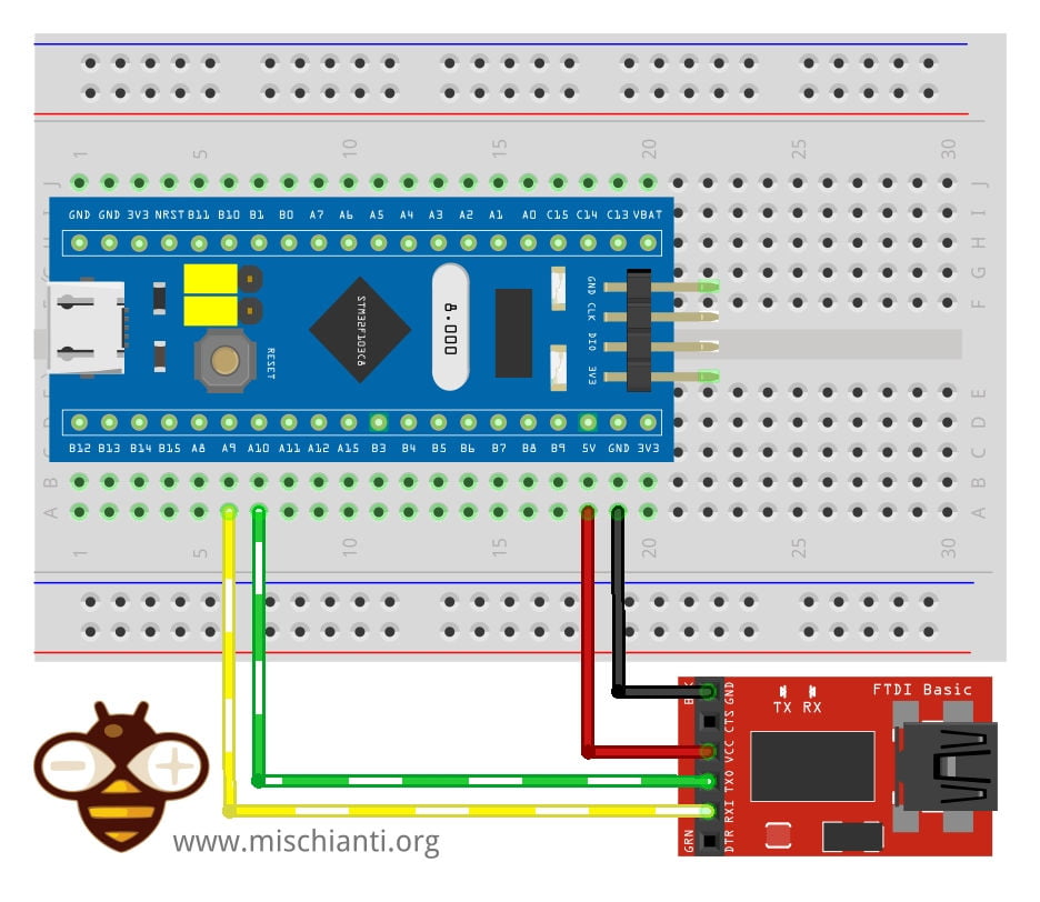
You can power the stm32 with 3.3v or 5v in the respective pin, and you must connect FTDI TX to PA10 and RX to PA9.
| STM32F103C8T6 | FTDI |
|---|---|
| 5v or 3.3v | VCC 5v or 3.3v |
| GND | GND |
| A9 | RX |
| A10 | TX |
Connection schema with ST-Link
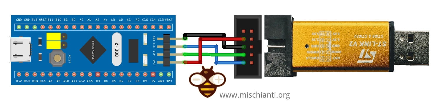
| STM32 | ST-Link v2 |
|---|---|
| GND | GND |
| SCK | SWCLK |
| DIO | SWDIO |
| 3V3 | 3V3 |
Boot modalities
You can select three types of boot mode:
- Boot from System Memory: that invokes the on-chip bootloader, which is present in the chip directly from the factory before you’ve programmed anything into the on-chip flash. This allows you to load (program) code into the device from an external interface such as UART or USB.
- Main flash memory: is where your code typically goes. In normal operation, your code will reside in flash, and on Power-On Reset (POR), the CPU will fetch the reset vector and initial stack pointer (SP) from flash. You can load flash via JTAG, the on-chip bootloader (above), etc.
- Load code into RAM (JTAG, runtime) and then boot/run from there. This isn’t often used, usually, you’re doing something tricky like a temporary bootloader or the like.
Here is the table with jumper configuration:
| BOOT0 | BOOT1 | Modality |
|---|---|---|
| 0 | X | Main flash memory |
| 1 | 0 | System Memory |
| 1 | 1 | Embedded SRAM |
Configure your Arduino IDE
Probably when you buy an STM32, It arrives without a bootloader, so nothing happens if you attach the device to the USB. So we must use an external device (FTDI described before) for the first programming or add a bootloader.
There are many board descriptors and firmware variants for STM32, and It’s pretty tricky to find a “standard” way to follow. So in this article, I’d like to add some options that you can choose.
SMT32duino
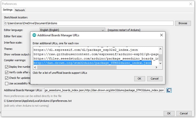
We start with stm32duino, probably the most famous. We must add the URL descriptor to our Arduino IDE.
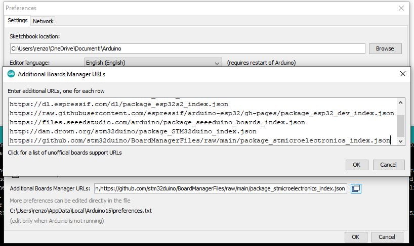
http://dan.drown.org/stm32duino/package_STM32duino_index.json
Go to File –> Preferences and add the URL on “Additional Boards Manager URLs.”
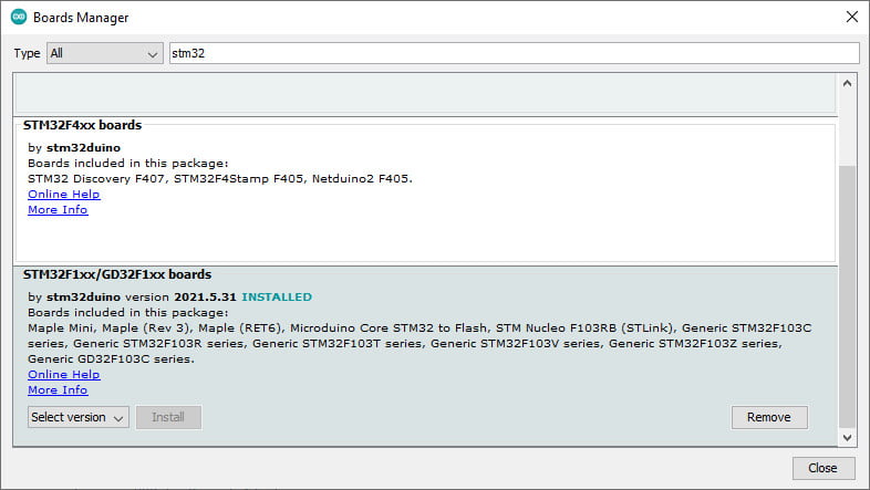
Then you must add a new board in Boards Manager
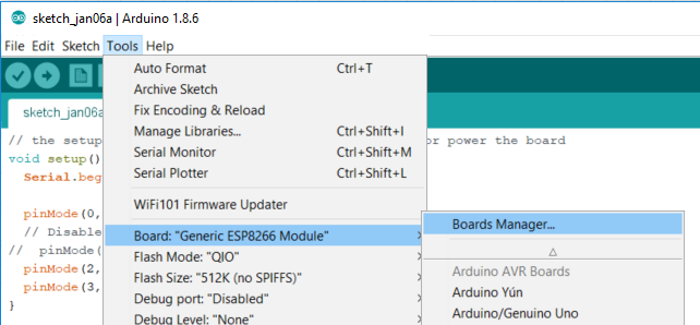
The board to select is STM32F1xx.
Now you can choose the specified device:
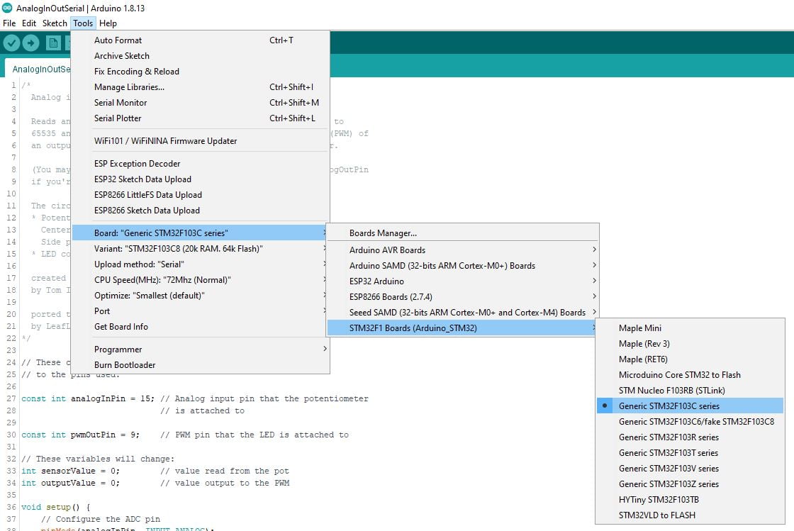
Now we are going to choose the upload method with Serial FTDI, so Upload method: "Serial".
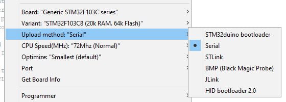
For the ST-Link you must select STLink.
Select boot mode
By default, you have jumpers in “normal” mode.

You must put it in “programming” mode (System memory).
Simple Blink sketch for STM32F1xx
My device has LED on PA13
/*
  Blink for STM32F1xx

  Turns an LED on for one second, then off for one second, repeatedly.

  http://www.mischianti.org
*/

void setup() {
  // Open serial communications and wait for port to open:
  Serial.begin(115200);

  while (!Serial) {
    ; // wait for serial port to connect. Needed for native USB port only
  }
  Serial.print(F("Serial OK!"));

  pinMode(PC13, OUTPUT);
}

void loop() {
  digitalWrite(PC13, HIGH);
  delay(1000);
  digitalWrite(PC13, LOW);
  delay(1000);
}
Now select the port of FDTI and start the upload.
C:\Users\renzo\AppData\Local\Arduino15\packages\stm32duino\tools\stm32tools\2021.5.31/win/serial_upload.bat COM25 {upload.altID} {upload.usbID} C:\Users\renzo\AppData\Local\Temp\arduino_build_965206/Blink.ino.bin
stm32flash 0.4

http://stm32flash.googlecode.com/

Using Parser : Raw BINARY
Interface serial_w32: 115200 8E1
Version      : 0x22
Option 1     : 0x00
Option 2     : 0x00
Device ID    : 0x0410 (Medium-density)
- RAM        : 20KiB  (512b reserved by bootloader)
- Flash      : 128KiB (sector size: 4x1024)
- Option RAM : 16b
- System RAM : 2KiB
Write to memory
Erasing memory
Wrote address 0x080032a4 (100.00%) Done.

Starting execution at address 0x08000000... done.
Now restore the jumper in the default position, push the “Reset” button, and the led start blink.
You must connect the Serial monitor to start the sketch.
Here is the Serial output.
Serial OK!
In the following articles, we will program the STM32 directly via a USB connector and STM32duino bootloader.
Arduino STM32 from STMicroelectronics
We must add the URL descriptor to our Arduino IDE.
https://github.com/stm32duino/BoardManagerFiles/raw/main/package_stmicroelectronics_index.json
Go to File –> Preferences and add the URL on “Additional Boards Manager URLs.”
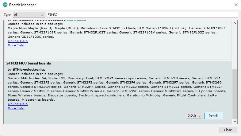
Then you must add a new board to Boards Manager
The boards to select are STM32 MCU-based boards.
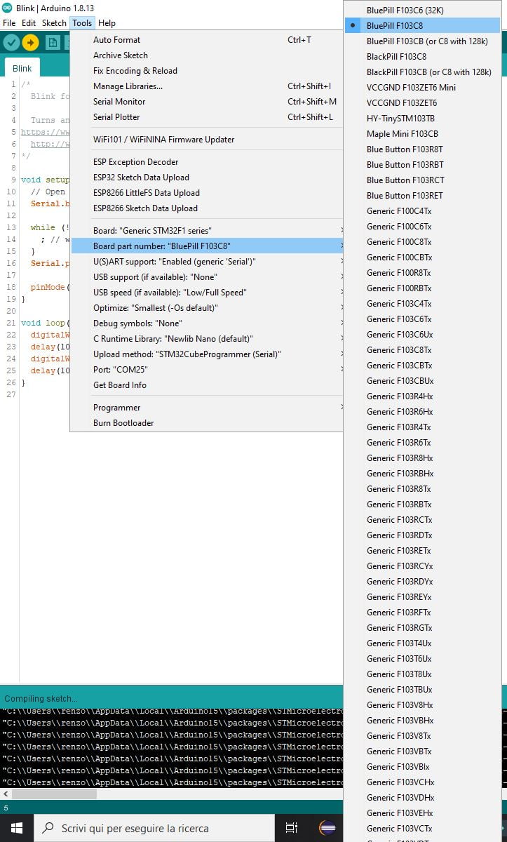
Now you can choose the specified device:
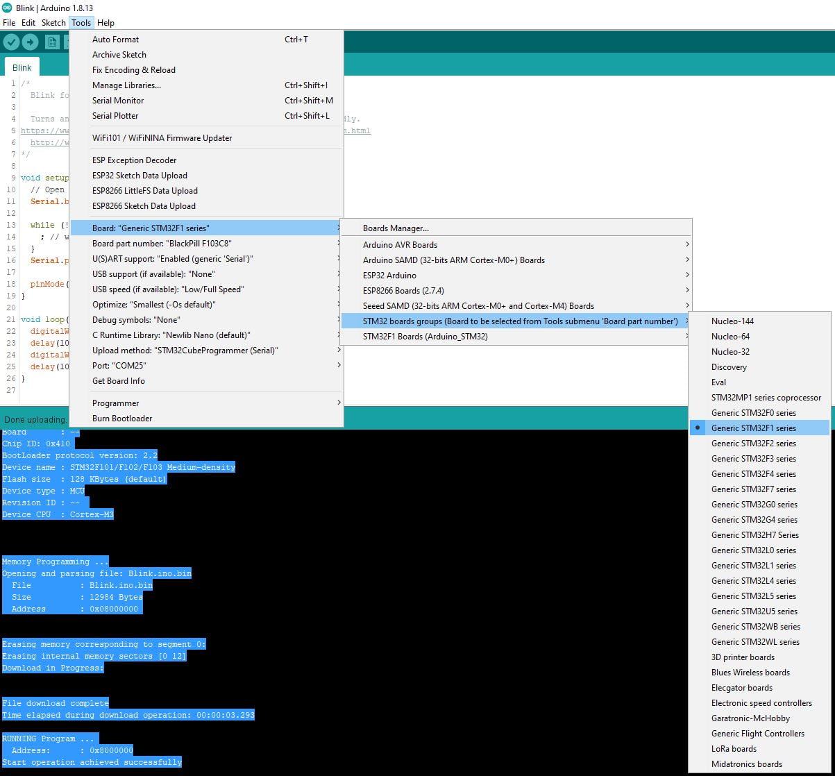
Now we are going to choose the specified board.
Now we are going to select the upload method with Serial FTDI, so Upload method: "Serial".
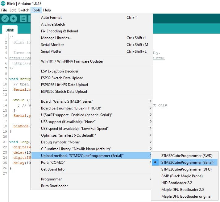
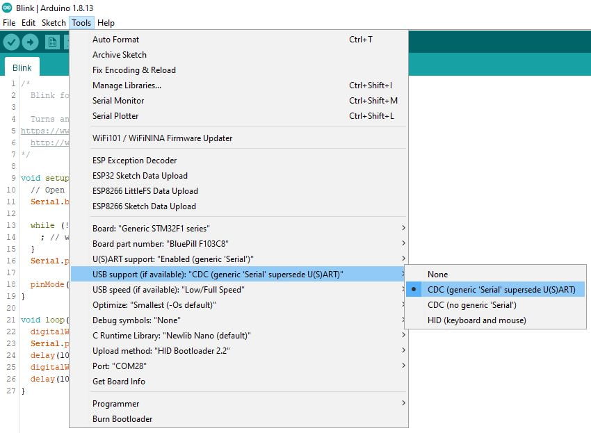
For ST-Link you must select STM32CubeProgrammer (SWD) and to debug you can use the serial adapter (and select USART support: Enabled (generic Serial) or you can select USB support (if available): CDC (generic ‘Serial’ supersede U(S)ART to use the USB cable.
Install STM32CubeProgrammer
To work, you also need to install the STM32CubeProgrammer released from STMicroelectronics.
You can download It from here.
Select boot mode
By default, you have jumpers in “normal” mode.
You must put it in “programming” mode (System memory).
Simple Blink sketch for STM32F1xx
My device has LED on PA13
/*
  Blink for STM32F1xx

  Turns an LED on for one second, then off for one second, repeatedly.

  http://www.mischianti.org
*/

void setup() {
  // Open serial communications and wait for port to open:
  Serial.begin(115200);

  while (!Serial) {
    ; // wait for serial port to connect. Needed for native USB port only
  }
  Serial.print(F("Serial OK!"));

  pinMode(PC13, OUTPUT);
}

void loop() {
  digitalWrite(PC13, HIGH);
  delay(1000);
  digitalWrite(PC13, LOW);
  delay(1000);
}
Now select the port of FDTI and start the upload.
Sketch uses 12692 bytes (19%) of program storage space. Maximum is 65536 bytes.
Global variables use 820 bytes (4%) of dynamic memory, leaving 19660 bytes for local variables. Maximum is 20480 bytes.
C:\Users\renzo\AppData\Local\Arduino15\packages\STMicroelectronics\tools\STM32Tools\2.1.1/win/busybox.exe sh C:\Users\renzo\AppData\Local\Arduino15\packages\STMicroelectronics\tools\STM32Tools\2.1.1/stm32CubeProg.sh 1 C:\Users\renzo\AppData\Local\Temp\arduino_build_965206/Blink.ino.bin COM25 -s
      -------------------------------------------------------------------
                       STM32CubeProgrammer v2.9.0
      -------------------------------------------------------------------

Serial Port COM25 is successfully opened.
Port configuration: parity = even, baudrate = 115200, data-bit = 8,
                     stop-bit = 1.0, flow-control = off
Activating device: OK
Board       : --
Chip ID: 0x410
BootLoader protocol version: 2.2
Device name : STM32F101/F102/F103 Medium-density
Flash size  : 128 KBytes (default)
Device type : MCU
Revision ID : --
Device CPU  : Cortex-M3


Memory Programming ...
Opening and parsing file: Blink.ino.bin
  File          : Blink.ino.bin
  Size          : 12984 Bytes
  Address       : 0x08000000


Erasing memory corresponding to segment 0:
Erasing internal memory sectors [0 12]
Download in Progress:


File download complete
Time elapsed during download operation: 00:00:03.293

RUNNING Program ...
  Address:      : 0x8000000
Start operation achieved successfully
Now restore the jumper in the default position, push the “Reset” button, and you must connect the Serial monitor. After that, the led starts to blink.
Here is the Serial output.
Serial OK!
In the following articles, we will program the STM32 directly via a USB connector and HID bootloader.
Thanks
- STM32F1 Blue-Pill: pinout, specs, and Arduino IDE configuration (STM32duino and STMicroelectronics)
- STM32: program (STM32F1) via USB with STM32duino bootloader
- STM32: programming (STM32F1 STM32F4) via USB with HID boot-loader
- STM32F4 Black-Pill: pinout, specs, and Arduino IDE configuration
- STM32: ethernet w5500 with plain HTTP and SSL (HTTPS)
- STM32: ethernet enc28j60 with plain HTTP and SSL (HTTPS)
- STM32: WiFiNINA with ESP32 WiFi Co-Processor
- How to use SD card with stm32 and SdFat library
- \STM32: SPI flash memory FAT FS
- STM32: internal RTC, clock, and battery backup (VBAT)
- STM32 LoRa
- STM32 Power saving
- STM32F1 Blue-Pill clock and frequency management
- STM32F4 Black-Pill clock and frequency management
- Intro and Arduino vs STM framework
- Library LowPower, wiring, and Idle (STM Sleep) mode
- Sleep, deep sleep, shutdown, and power consumption
- Wake up from RTC alarm and Serial
- Wake up from the external source
- Backup domain intro and variable preservation across reset
- RTC backup register and SRAM preservation
- STM32 send emails with attachments and SSL (like Gmail): w5500, enc28j60, SD, and SPI Fash