ESP32-CAM: pinout, specs and Arduino IDE configuration – 1
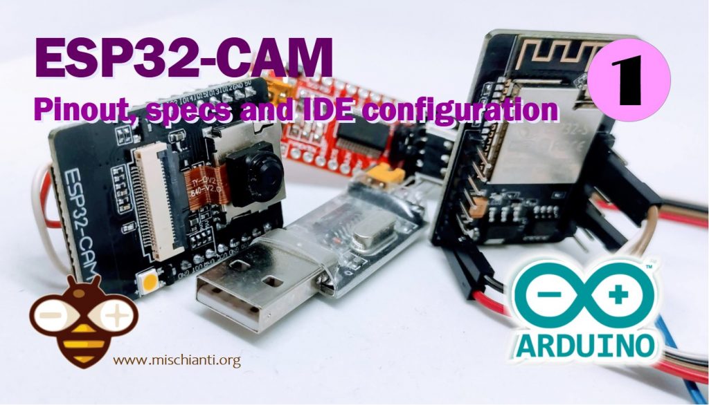
ESP32-CAM details
This device It’s very powerful with WIFI Bluetooth but overall a 2Mp camera.
You can find It here ESP32 Dev Kit v1 - TTGO T-Display 1.14 ESP32 - NodeMCU V3 V2 ESP8266 Lolin32 - NodeMCU ESP-32S - WeMos Lolin32 - WeMos Lolin32 mini - ESP32-CAM programmer - ESP32-CAM bundle - ESP32-WROOM-32 - ESP32-S
Specs
Here is the chart of all functional units of this microcontroller.
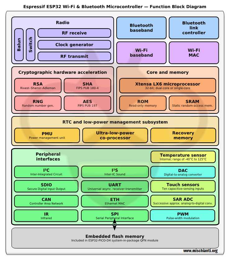
- Processors:
- CPU: Xtensa dual-core 32-bit LX6 microprocessor, operating at 240 MHz and performing at up to 600 DMIPS
- Ultra low power (ULP) co-processor
- Memory: 520 KiB SRAM, external 4M PSRAM
- Wireless connectivity:
- Wi-Fi: 802.11 b/g/n
- Bluetooth: v4.2 BR/EDR and BLE (shares the radio with Wi-Fi)
- Support OV2640 and OV7670 cameras, built-in flash
- Support TF card
- Security:
- IEEE 802.11 standard security features all supported, including WFA, WPA/WPA2 and WAPI
- Secure boot
- Flash encryption
- 1024-bit OTP, up to 768-bit for customers
- Cryptographic hardware acceleration: AES, SHA-2, RSA, elliptic curve cryptography (ECC), random number generator (RNG)
- Power management:
- Internal low-dropout regulator
- Individual power domain for RTC
- 5μA deep sleep current
- Wake up from GPIO interrupt, timer, ADC measurements, capacitive touch sensor interrupt
Pinouts
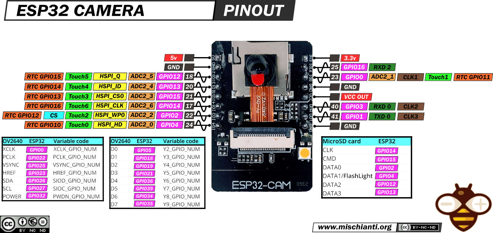
This device is potent, but you can use a shallow set of pins; the major part is used for the camera, and part of others for SD.
Usage
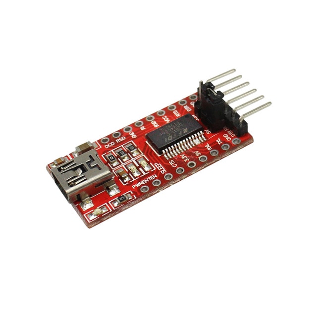
This device doesn’t have an installed USB to TTL converter, so you need an FTDI programmer. I usually use a basic model, but in this case, It’s more simple to use a module with integrated power possibility.
It exists more expensive FT232RL or FT232 module, but a CH340G or CH340 working very well.
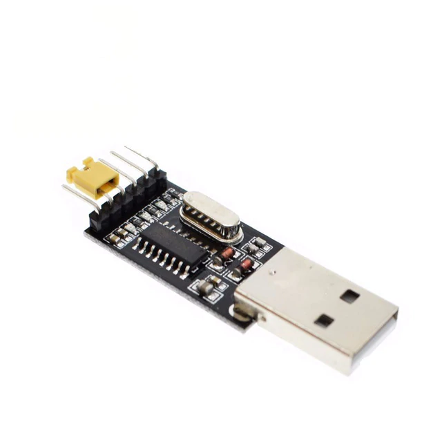
Here the two model USB to TTL CH340G - USB to TTL FT232RL
Connection schema
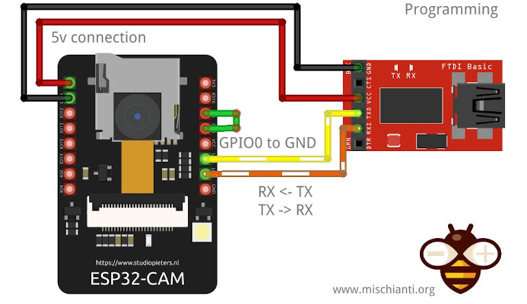
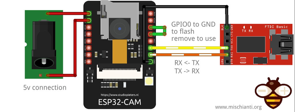
ESP32-CAM doesn’t have a built-in USB port with a UART converter, so you must use your FTDI. Here is an example of connection schema to 5v pin:
Here is a connection schema with a 3.3v voltage setting.
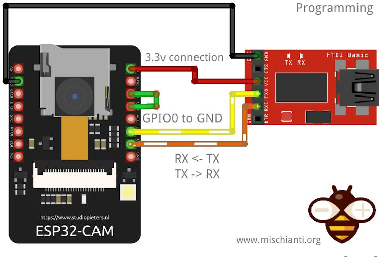
As you can see, there is a jumper from GPIO0, and GNDThis is needed to upload the sketch. When the sketch is uploaded, remove that to use the device.
For me, you can connect (and configure the FTDI) at 3.3v pin or to 5v pin, working correctly with all configurations.
If the power isn’t sufficient, you receive a “Brownout detector was triggered“
But to use It, you must connect an external power like this.
The “Brownout detector was triggered” error can be avoided; next, I explain better.
Without stream, the device consumes 80mAh, and when streaming the content, it’s about 100~160mAh; if you activate flash can raise 270mAh.
| Operation mode | Power |
|---|---|
| Stand by | 80mHa |
| In streaming | 100~160mAh |
| In streaming with flash | 270mAh |
Configure your ide
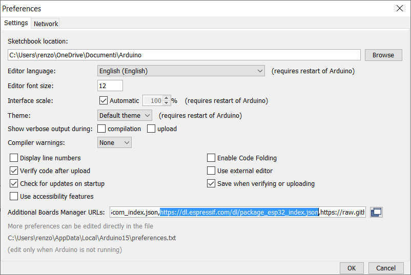
First, you must add esp32 URL descriptor to your IDE
https://dl.espressif.com/dl/package_esp32_index.json
Go to File –> Preferences and add the URL on “Additional Boards Manager URLs.”
Then you must add a new board in Boards Manager
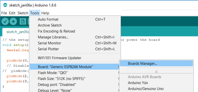
The boards to select is esp32
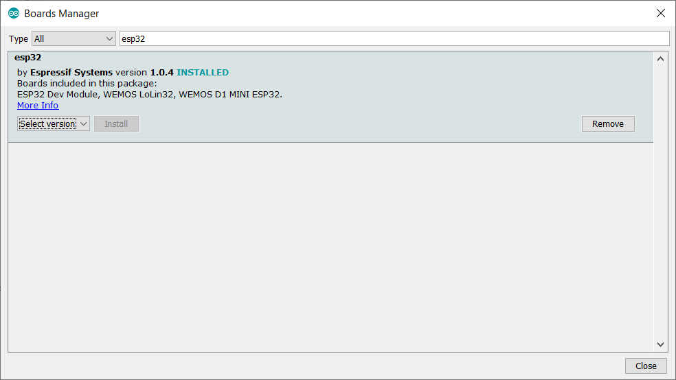
Now you can select AI Thinker ESP32-CAM Dev Module
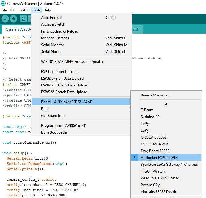
And upload your sketch.
Modify the sketch CameraWebServer for the CLONE version of ESP32-CAM
No more available from the ESP32 2.x.x Framework.
There is a beautiful example for ESP32-CAM on the default ESP32 board package.
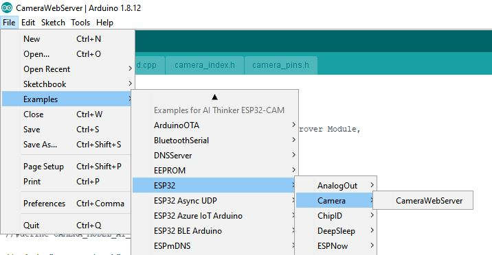
If you buy generic ESP32-CAM on the Chinese market or from some supplier, you will probably have to change the configuration in this way.
First, you must uncomment the correct clone model:
// Select camera model
//#define CAMERA_MODEL_WROVER_KIT
//#define CAMERA_MODEL_ESP_EYE
//#define CAMERA_MODEL_M5STACK_PSRAM
//#define CAMERA_MODEL_M5STACK_WIDE
#define CAMERA_MODEL_AI_THINKER
Brownout detector was triggered
After loading, you may get an error in the serial monitor with this message, which means that the power supply you use offers enough power.
ets Jun  8 2016 00:22:57

rst:0xc (SW_CPU_RESET),boot:0x13 (SPI_FAST_FLASH_BOOT)
configsip: 0, SPIWP:0xee
clk_drv:0x00,q_drv:0x00,d_drv:0x00,cs0_drv:0x00,hd_drv:0x00,wp_drv:0x00
mode:DIO, clock div:1
load:0x3fff0018,len:4
load:0x3fff001c,len:1216
ho 0 tail 12 room 4
load:0x40078000,len:9720
ho 0 tail 12 room 4
load:0x40080400,len:6352
entry 0x400806b8


Brownout detector was triggered
you can try to connect to an external power supply or add this line to the setup with the correct include
  #include "soc/soc.h"
  #include "soc/rtc_cntl_reg.h"
[...]
setup() {
  WRITE_PERI_REG(RTC_CNTL_BROWN_OUT_REG, 0); //disable brownout detector
remember to set your SSID and password
const char* ssid = "<YOUR-SSID>";
const char* password = "<YOUR-PASSWD>";
The complete code of the sketch looks like this.
#include "esp_camera.h"
#include <WiFi.h>
#include "soc/soc.h"
#include "soc/rtc_cntl_reg.h"

//
// WARNING!!! Make sure that you have either selected ESP32 Wrover Module,
//            or another board which has PSRAM enabled
//

// Select camera model
//#define CAMERA_MODEL_WROVER_KIT
//#define CAMERA_MODEL_ESP_EYE
//#define CAMERA_MODEL_M5STACK_PSRAM
//#define CAMERA_MODEL_M5STACK_WIDE
#define CAMERA_MODEL_AI_THINKER

#include "camera_pins.h"

const char* ssid = "<YOUR-SSID>";
const char* password = "<YOUR-PASSWD>";

void startCameraServer();

void setup() {
  WRITE_PERI_REG(RTC_CNTL_BROWN_OUT_REG, 0); //disable brownout detector

  Serial.begin(115200);
  Serial.setDebugOutput(true);
  Serial.println();

  camera_config_t config;
  config.ledc_channel = LEDC_CHANNEL_0;
  config.ledc_timer = LEDC_TIMER_0;
  config.pin_d0 = Y2_GPIO_NUM;
  config.pin_d1 = Y3_GPIO_NUM;
  config.pin_d2 = Y4_GPIO_NUM;
  config.pin_d3 = Y5_GPIO_NUM;
  config.pin_d4 = Y6_GPIO_NUM;
  config.pin_d5 = Y7_GPIO_NUM;
  config.pin_d6 = Y8_GPIO_NUM;
  config.pin_d7 = Y9_GPIO_NUM;
  config.pin_xclk = XCLK_GPIO_NUM;
  config.pin_pclk = PCLK_GPIO_NUM;
  config.pin_vsync = VSYNC_GPIO_NUM;
  config.pin_href = HREF_GPIO_NUM;
  config.pin_sscb_sda = SIOD_GPIO_NUM;
  config.pin_sscb_scl = SIOC_GPIO_NUM;
  config.pin_pwdn = PWDN_GPIO_NUM;
  config.pin_reset = RESET_GPIO_NUM;
  config.xclk_freq_hz = 20000000;
  config.pixel_format = PIXFORMAT_JPEG;
  //init with high specs to pre-allocate larger buffers
  if(psramFound()){
    config.frame_size = FRAMESIZE_UXGA;
    config.jpeg_quality = 10;
    config.fb_count = 2;
  } else {
    config.frame_size = FRAMESIZE_SVGA;
    config.jpeg_quality = 12;
    config.fb_count = 1;
  }

#if defined(CAMERA_MODEL_ESP_EYE)
  pinMode(13, INPUT_PULLUP);
  pinMode(14, INPUT_PULLUP);
#endif

  // camera init
  esp_err_t err = esp_camera_init(&config);
  if (err != ESP_OK) {
    Serial.printf("Camera init failed with error 0x%x", err);
    return;
  }

  sensor_t * s = esp_camera_sensor_get();
  //initial sensors are flipped vertically and colors are a bit saturated
  if (s->id.PID == OV3660_PID) {
    s->set_vflip(s, 1);//flip it back
    s->set_brightness(s, 1);//up the blightness just a bit
    s->set_saturation(s, -2);//lower the saturation
  }
  //drop down frame size for higher initial frame rate
  s->set_framesize(s, FRAMESIZE_QVGA);

#if defined(CAMERA_MODEL_M5STACK_WIDE)
  s->set_vflip(s, 1);
  s->set_hmirror(s, 1);
#endif

  WiFi.begin(ssid, password);

  while (WiFi.status() != WL_CONNECTED) {
    delay(500);
    Serial.print(".");
  }
  Serial.println("");
  Serial.println("WiFi connected");

  startCameraServer();

  Serial.print("Camera Ready! Use 'http://");
  Serial.print(WiFi.localIP());
  Serial.println("' to connect");
}

void loop() {
  // put your main code here, to run repeatedly:
  delay(10000);
}
If It’s all ok, you receive this message on Serial output:
.
WiFi connected
Starting web server on port: '80'
Starting stream server on port: '81'
Camera Ready! Use 'http://192.168.1.171' to connect
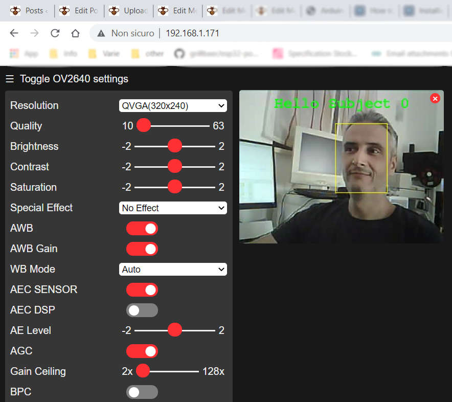
And here is the result in the web page for the URL http://192.168.1.171
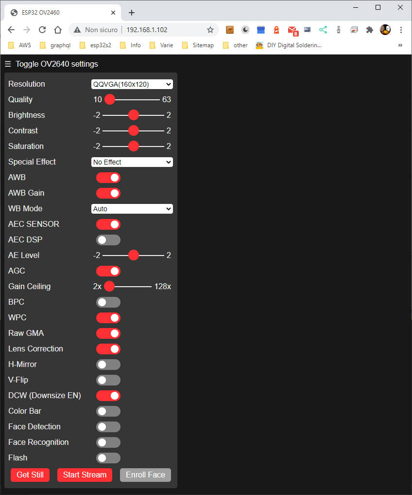
but you can find the IP stream on http://192.168.1.171:81/stream (to use with other programs).
This basic example has some exciting features like the management of face recognition, you can enable face recognition, and first, you are detected as a malicious “intruder”:
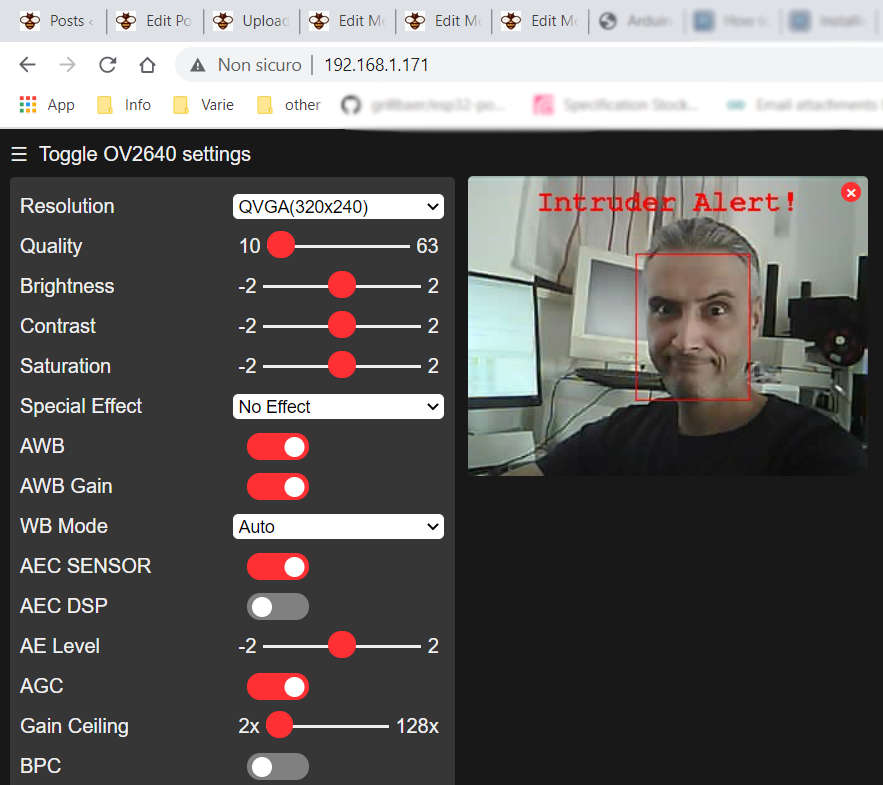
but if you enroll your face (with the relative button), you become safe people
Thanks
- ESP32-CAM: pinout, specs and Arduino IDE configuration
- ESP32-CAM: upgrade CamerWebServer with flash feature
- ESP32-CAM: control CameraWebServer from your own web page
Firmware with additional features.