
Ciclop 3D scanner: production and assembly of the control PCB – 2
In this article I would like to show my custom PCB for the Ciclop 3D scanner which is fully compatible with the original ZUM.
I made my own PCB to replace the original ZUM SCAN one (bigger and more expensive). I also share it on PCBWay.
Ciclop 3D scanner board v1.2 PCBWay

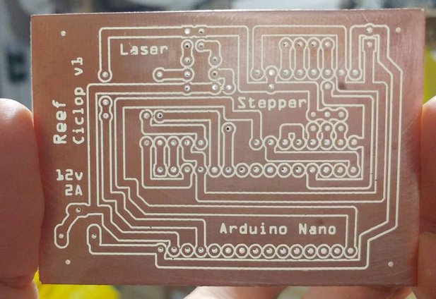
PCB v1.0
This is a fully functional version (videos are made with this version) and it was the simplest. In version v1.2 I thought about adding a resettable PTC to avoid burning the engine (it never happens usually), I made my version with an old Epson Stylus Color 460 stepper motor.
I wrote a guide on how to reuse the old stepper motor “How to reuse 4 and 6 wires stepper motors for your projects“
As I said, the PCB is fully compatible with the original one. Zum scan is more complex, but all additional features is unused.
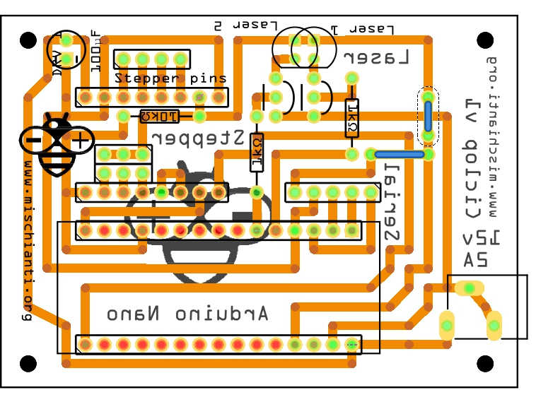
My version is for Arduino Nano, so It’s more little than the original one.
PCB Etching
I never used this technic, but I add to this step the svg file or PDF for production.
Milling PCB
I use this technic for my personal production, I think you can find interesting this series of articles “Cyclone PCB factory: how to build It” and “Milling PCB tutorial“.
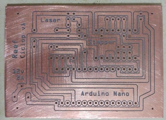
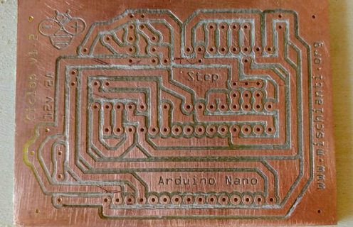
Milling PCB: the Milling Process
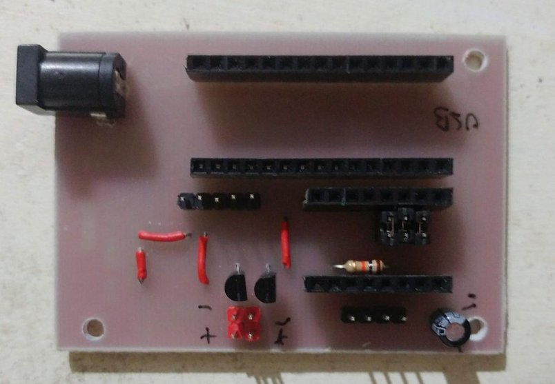
First mill the copper bottom, then drill the holes.
Here the first traces pass.
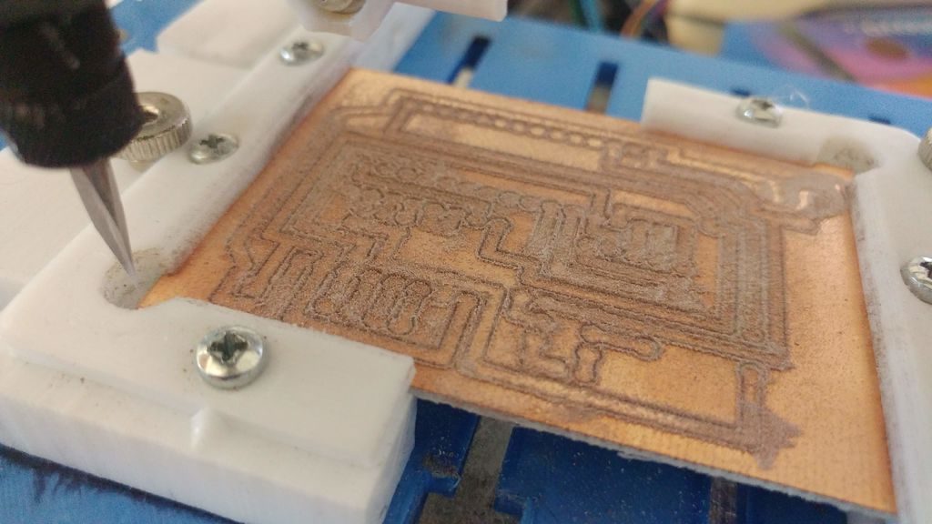
And the finished work.
Milling PCB: clean the milled PCB
Than use sand paper to made the board flat and clean. This is my first version, in the next paragraph I add the updated version.
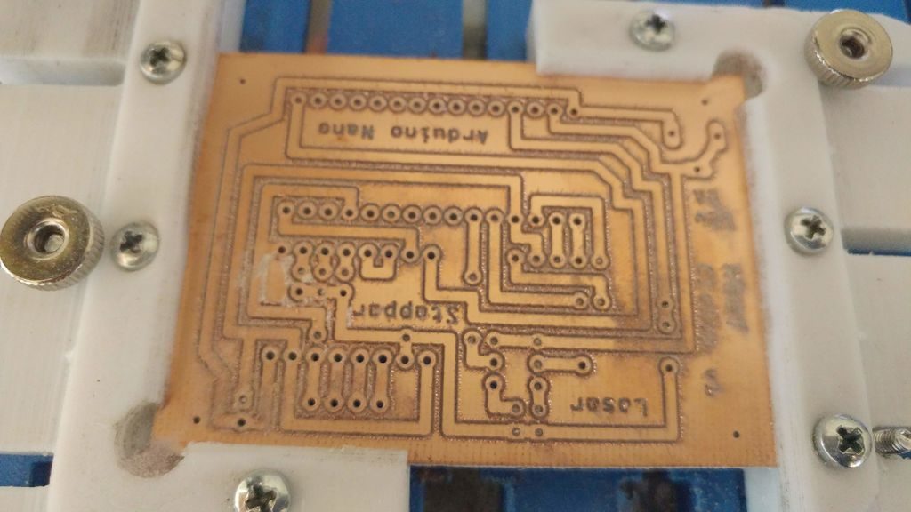
PCB v1.2
As I said, I later created a PTC resettable fuse board, (1.85A 30V) this simple component protects your stepper from the current problem. This card is fully compatible with the original one.
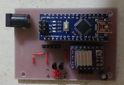
So to test the board I restart the whole milling process and here is the result
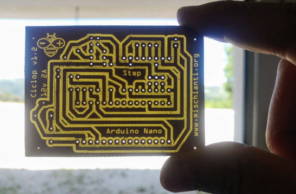
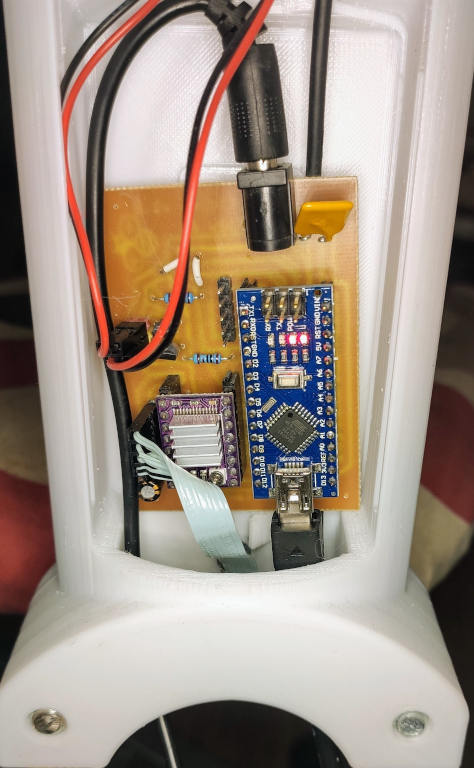
Here the new board active and mounted.
Order 10 PCBs for 5$ on PCBWay
You can order the PCB at PCBWay for few dollars here
Ciclop 3D scanner board v1.2 PCBWay
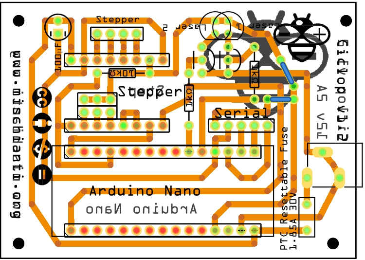
PCB Assembly
Complete BOM
Here is the list of components.
| 2 | 1kΩ Resistor |
| 1 | 100µF Electrolytic Capacitor |
| 1 | DRV 8825 (with one divider jumper) or a4988 Stepper Motor Carrier |
| 2 | Generic female header – 15 pins |
| 2 | Generic female header – 8 pins |
| 1 | Generic male header – 4 pins |
| 2 | Generic male header – 3 pins |
| 1 | Barrel 5.5 power Jack (breadboard friendly) |
| 1 | Generic female header – 5 pins |
| 2 | Red (633nm) LED |
| 1 | Arduino Nano (Rev3.0) |
| 1 | 1.85A 30V Resettable Fuse PTC (Not needed on v1.0 board) |
| 2 | NPN-Transistor 2n2222a |
| 1 | 10kΩ Resistor |
And here the links to the less common components
- Arduino Nano
You can find It here AliExpress
- A4988 Stepper driver
- 2x 1k resistor
- 1x 10k resistor
- 2x 2n2222 transistor
- 5.5 Barrel for input voltage
Barrel Jack breadboard friendly on Aliexpress Breadboard friendly 5.5x2.1 - Aliexpress 5.5x2.1
- In the new board you need only one more component the PTC Resettable fuse 30v 1.85A
Solder the components on the milled PCB
Now we add the components to the board after the assembly process.
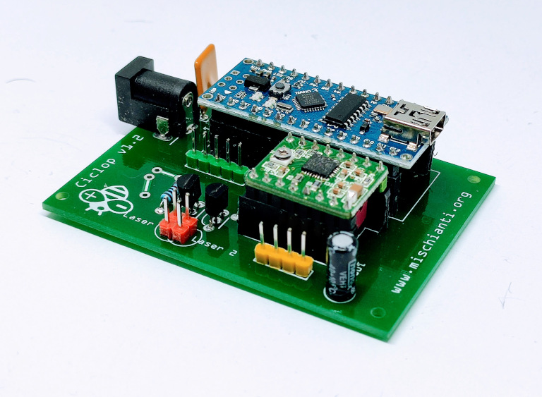
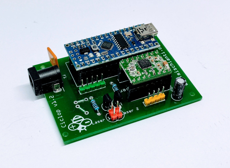
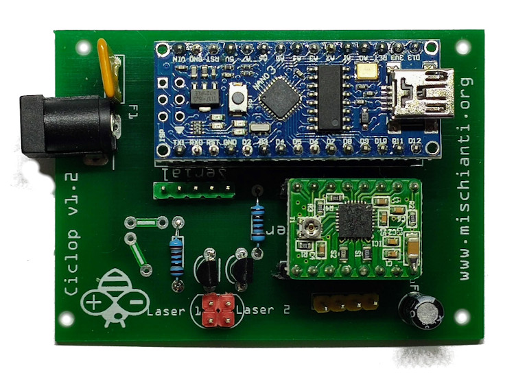
Here the PCB from PCBWay.

And here the result.
And here the finished PCB with compoents.
Now we must start to add all electronic cable, I explain how to in the next article.
I use 12v 2A power supply (to the barrel) to power a stepper driver.
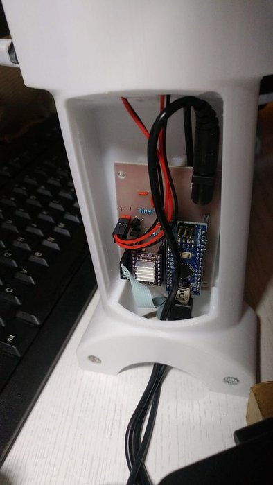
The USB connector is sufficient for laser and Arduino, but the power supply is for the stepper.
Thanks
- Ciclop 3D scanner: component printing and assembly
- Ciclop 3D scanner: production and assembly of the control PCB
- Ciclop 3D scanner: assembling electronic and wiring
- Ciclop 3D scanner: componens testing and calibration


Hi Renzo, can you please help me in getting the firmware for this project…?
Hi Narashima,
you can find it here.
Ciclop 3D scanner: components testing and calibration – 4
Bye Renzo
I am actually a student and I am doing this as my academic project, so if the firmware pin declaration and the pin configuration of your pcb is same means please share the schematic of the pcb so that I can understand and make connections properly…
Thanks regards Renzo 🙏
Hi Narasimha,
sorry, but I did this project some years ago, so It’s difficult for me to retrieve the material.
But in the articles, you can find a lot of information.
Bye Renzo