
SDD1306 OLED display: wiring and basic use with esp8266, esp32 and Arduino – 1
SSD1306 IC is used for the most commons OLED display is a single-chip CMOS OLED/PLED driver with controller for organic / polymer light emitting diode dot-matrix graphic display system. It consists of 128 segments and 64 commons.
The SSD1306 embeds with contrast control, display RAM and oscillator, which reduces the number of external components and power consumption. It has 256-step brightness control. Data/Commands are sent from general MCU through the hardware selectable 6800/8000 series compatible Parallel Interface, I2C interface or Serial Peripheral Interface.
ssd1306 OLED Display on AliExpress I2C SPI SSD1306 0.91 0.96 inch OLED
Features
- Resolution: 128 x 64 dot matrix panel or 128 x 32
- Power supply
- VDD = 1.65V to 3.3V for IC logic
- VCC = 7V to 15V for Panel driving
- For matrix display
- OLED driving output voltage, 15V maximum
- Segment maximum source current: 100uA
- Common maximum sink current: 15mA
- 256 step contrast brightness current control
- Embedded 128 x 64 bit SRAM display buffer
- Pin selectable MCU Interfaces:
- 8-bit 6800/8080-series parallel interface
- 3 /4 wire Serial Peripheral Interface
- I2C Interface
- Screen saving continuous scrolling function in both horizontal and vertical direction
- RAM write synchronization signal
- Programmable Frame Rate and Multiplexing Ratio
- Row Re-mapping and Column Re-mapping
- On-Chip Oscillator
- Chip layout for COG & COF
- Wide range of operating temperature: -40°C to 85°C
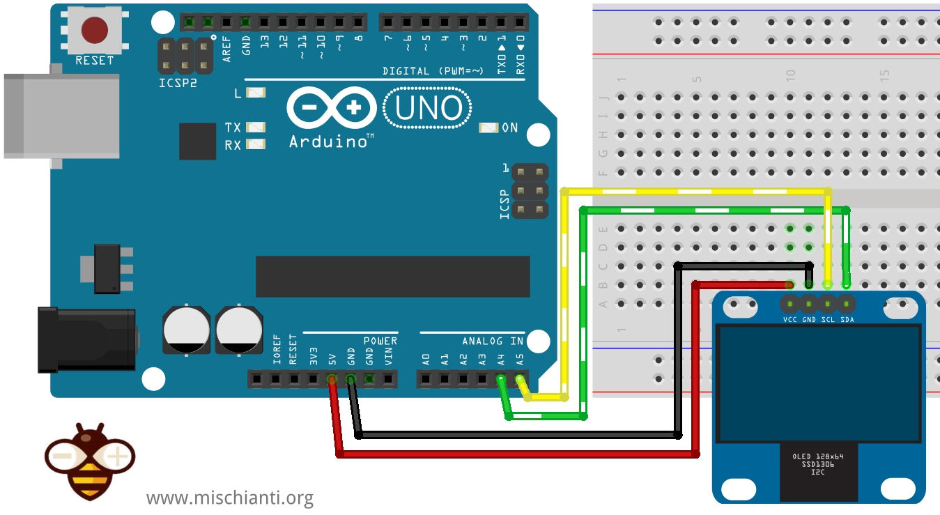
Wiring i2c
Arduino
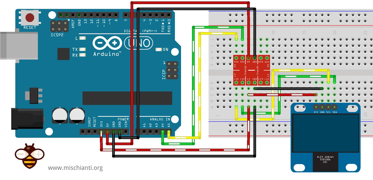
Remember Arduino work on 5v, so if your version of Oled don’t support 5v logic you must put in the middle a logic level converter.
Here a logic level converter Aliexpress
The constructor is quite simple:
/*
 * Arduino UNO 	<--> 	Oled
 * 3.3v					VCC
 * GND					GND
 * A4					SDA
 * A5					SCL
 */

#define SCREEN_WIDTH 128 // OLED display width, in pixels
#define SCREEN_HEIGHT 64 // OLED display height, in pixels

// Declaration for an SSD1306 display connected to I2C (SDA, SCL pins)
#define OLED_RESET     -1 // Reset pin # (or -1 if sharing Arduino reset pin)
Adafruit_SSD1306 display(SCREEN_WIDTH, SCREEN_HEIGHT, &Wire, OLED_RESET);

[...]

  // SSD1306_SWITCHCAPVCC = generate display voltage from 3.3V internally
  if(!display.begin(SSD1306_SWITCHCAPVCC, 0x3C)) {
    Serial.println(F("SSD1306 allocation failed"));
    for(;;); // Don't proceed, loop forever
  }
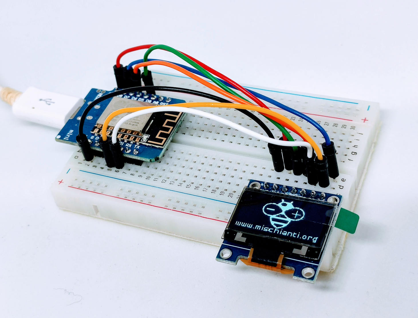
esp8266
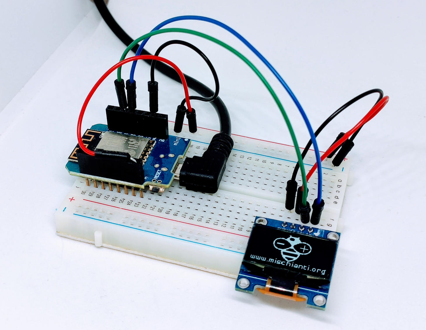
For ESP32 and esp8266 is more simple, because the work at 3.3v. So no need of converter.
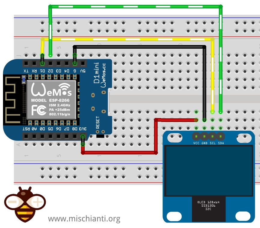
The code is the same of Arduino, only wiring (with i2c standard) change:
/*
 * WeMos D1	<--> 	Oled
 * 3.3v					VCC
 * GND					GND
 * D2					SDA
 * D1					SCL
 */

#define SCREEN_WIDTH 128 // OLED display width, in pixels
#define SCREEN_HEIGHT 64 // OLED display height, in pixels

// Declaration for an SSD1306 display connected to I2C (SDA, SCL pins)
#define OLED_RESET     -1 // Reset pin # (or -1 if sharing Arduino reset pin)
Adafruit_SSD1306 display(SCREEN_WIDTH, SCREEN_HEIGHT, &Wire, OLED_RESET);

[...]

  // SSD1306_SWITCHCAPVCC = generate display voltage from 3.3V internally
  if(!display.begin(SSD1306_SWITCHCAPVCC, 0x3C)) {
    Serial.println(F("SSD1306 allocation failed"));
    for(;;); // Don't proceed, loop forever
  }
esp32
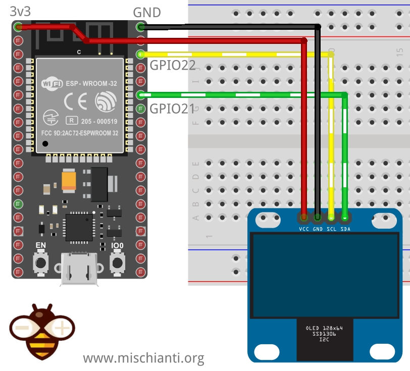
/*
 * ESP32	<--> 	Oled
 * 3.3v					VCC
 * GND					GND
 * 21					SDA
 * 22					SCL
 */

#define SCREEN_WIDTH 128 // OLED display width, in pixels
#define SCREEN_HEIGHT 64 // OLED display height, in pixels

// Declaration for an SSD1306 display connected to I2C (SDA, SCL pins)
#define OLED_RESET     -1 // Reset pin # (or -1 if sharing Arduino reset pin)
Adafruit_SSD1306 display(SCREEN_WIDTH, SCREEN_HEIGHT, &Wire, OLED_RESET);

[...]

  // SSD1306_SWITCHCAPVCC = generate display voltage from 3.3V internally
  if(!display.begin(SSD1306_SWITCHCAPVCC, 0x3C)) {
    Serial.println(F("SSD1306 allocation failed"));
    for(;;); // Don't proceed, loop forever
  }
Wiring SPI
Arduino
For SPI you must connect more wire, not only the SPI one but also RST and DC pin. Remember that Arduino had 5v logic level, so you must check if your display support that voltage.
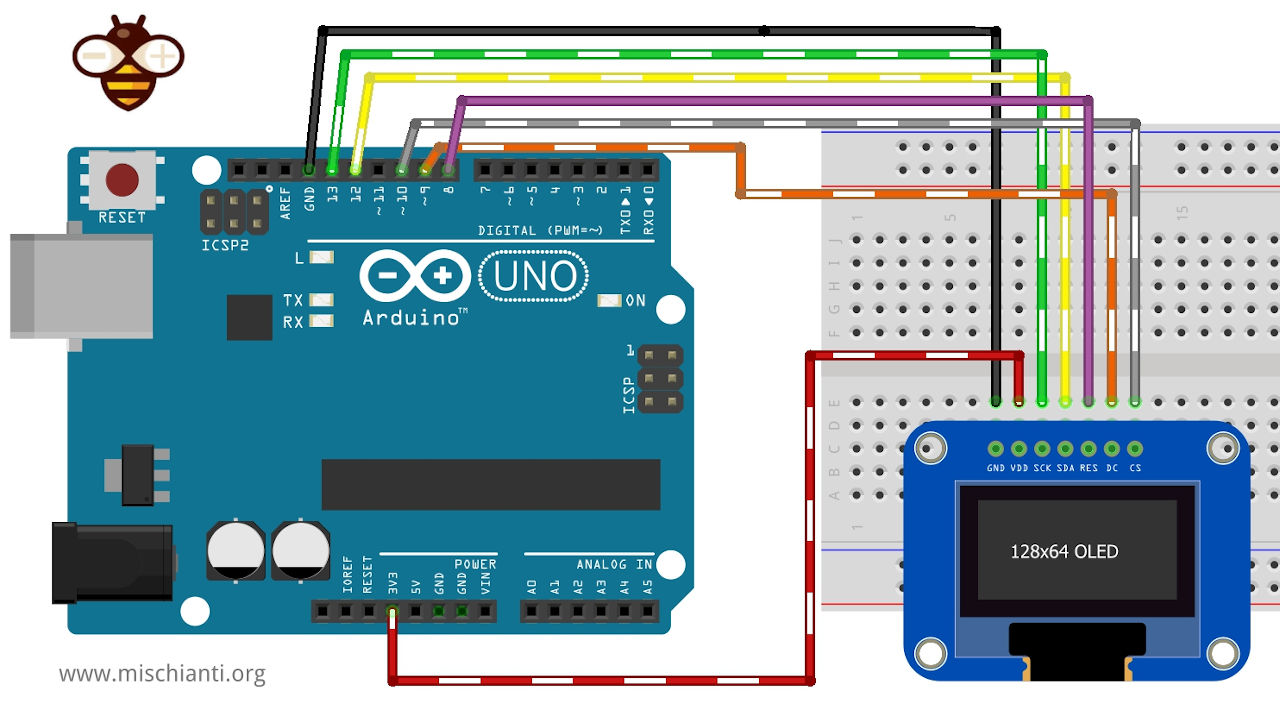
// Declaration for SSD1306 display connected using software SPI (default case):
#define OLED_MOSI   12
#define OLED_CLK   13
#define OLED_DC    9
#define OLED_CS    10
#define OLED_RESET 6
Adafruit_SSD1306 display(SCREEN_WIDTH, SCREEN_HEIGHT, OLED_MOSI, OLED_CLK, OLED_DC, OLED_RESET, OLED_CS);

[...]

  // SSD1306_SWITCHCAPVCC = generate display voltage from 3.3V internally
  if(!display.begin(SSD1306_SWITCHCAPVCC)) {
    Serial.println(F("SSD1306 allocation failed"));
    for(;;); // Don't proceed, loop forever
  }
esp8266
For esp8266 and esp32 is more simple because they have native 3.3v logic.
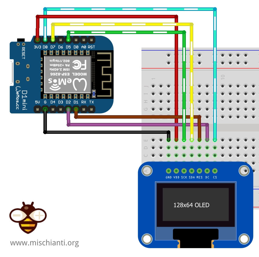
// Declaration for SSD1306 display connected using software SPI (default case):
#define OLED_MOSI   D7
#define OLED_CLK   D5
#define OLED_DC    D2
#define OLED_CS    D8
#define OLED_RESET D1
Adafruit_SSD1306 display(SCREEN_WIDTH, SCREEN_HEIGHT, OLED_MOSI, OLED_CLK, OLED_DC, OLED_RESET, OLED_CS);

[...]

  // SSD1306_SWITCHCAPVCC = generate display voltage from 3.3V internally
  if(!display.begin(SSD1306_SWITCHCAPVCC)) {
    Serial.println(F("SSD1306 allocation failed"));
    for(;;); // Don't proceed, loop forever
  }
esp32
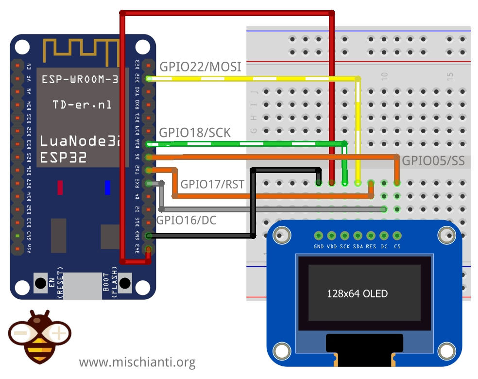
// Declaration for SSD1306 display connected using software SPI (default case):
#define OLED_MOSI   22
#define OLED_CLK   18
#define OLED_DC    16
#define OLED_CS    5
#define OLED_RESET 17
Adafruit_SSD1306 display(SCREEN_WIDTH, SCREEN_HEIGHT, OLED_MOSI, OLED_CLK, OLED_DC, OLED_RESET, OLED_CS);

[...]

  // SSD1306_SWITCHCAPVCC = generate display voltage from 3.3V internally
  if(!display.begin(SSD1306_SWITCHCAPVCC)) {
    Serial.println(F("SSD1306 allocation failed"));
    for(;;); // Don't proceed, loop forever
  }
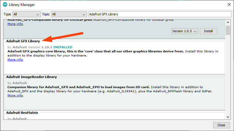
Adafruit Library
Among the best libraries there are always those of Adafruit, Adafruit’s objectives are always simplicity and completeness.
You can find It on GitHub or download via Arduino IDE library manager.
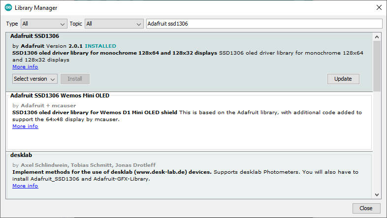
This library have 2 dependencies Adafruit BusIO
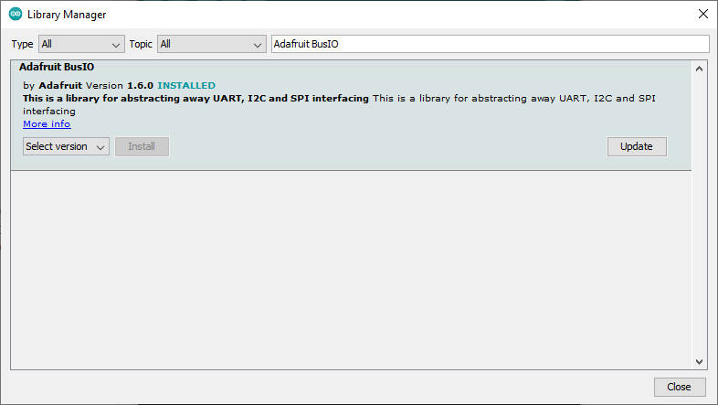
and Adafruit GFX library.
Display basics
You can find the following information at the Adafruit site with a lot of addiction, I copy here a subset to give a simple basic information to start, and I integrate with some other tips.
Coordinate System and Units
Pixels (picture elements, the blocks comprising a digital image) are addressed by their horizontal (X) and vertical (Y) coordinates. The coordinate system places the origin (0,0) at the top left corner, with positive X increasing to the right and positive Y increasing downward. To use a tall “portrait” layout rather than wide “landscape” format, or if physical constraints dictate the orientation of a display in an enclosure, one of four rotation settings can also be applied, indicating which corner of the display represents the top left.

The colors are 1 (set) or 0 (transparent). The semantics of a set / clear OLED display is “set” illuminator “clear” no.
Graphics Primitives
Here a set of standard and cross display commands.
Drawing pixels (points)
First up is the most basic pixel pusher. You can call this with X, Y coordinates and a color and it will make a single dot:
void drawPixel(uint16_t x, uint16_t y, uint16_t color);
Drawing lines
You can also draw lines, with a starting and end point and color:
void drawLine(uint16_t x0, uint16_t y0, uint16_t x1, uint16_t y1, uint16_t color);

For horizontal or vertical lines, there are optimized line-drawing functions that avoid the angular calculations:
void drawFastVLine(uint16_t x0, uint16_t y0, uint16_t length, uint16_t color);
void drawFastHLine(uint8_t x0, uint8_t y0, uint8_t length, uint16_t color);
Rectangles
Next up, rectangles and squares can be drawn and filled using the following procedures. Each accepts an X, Y pair for the top-left corner of the rectangle, a width and height (in pixels), and a color. drawRect() renders just the frame (outline) of the rectangle while fillRect() fills the entire area with a given color:
void drawRect(uint16_t x0, uint16_t y0, uint16_t w, uint16_t h, uint16_t color);void fillRect(uint16_t x0, uint16_t y0, uint16_t w, uint16_t h, uint16_t color);

To create a solid rectangle with a contrasting outline, use fillRect() first, then drawRect() over it.
Circles
Likewise, for circles, you can draw and fill. Each function accepts an X, Y pair for the center point, a radius in pixels, and a color:
void drawCircle(uint16_t x0, uint16_t y0, uint16_t r, uint16_t color);
void fillCircle(uint16_t x0, uint16_t y0, uint16_t r, uint16_t color);

Rounded rectangles
For rectangles with rounded corners, both draw and fill functions are again available. Each begins with an X, Y, width and height (just like normal rectangles), then there’s a corner radius (in pixels) and finally the color value:
void drawRoundRect(uint16_t x0, uint16_t y0, uint16_t w, uint16_t h, uint16_t radius, uint16_t color);
void fillRoundRect(uint16_t x0, uint16_t y0, uint16_t w, uint16_t h, uint16_t radius, uint16_t color);

Here’s an added bonus trick: because the circle functions are always drawn relative to a center pixel, the resulting circle diameter will always be an odd number of pixels.
Triangles
With triangles, once again there are the draw and fill functions. Each requires a full seven parameters: the X, Y coordinates for three corner points defining the triangle, followed by a color:
void drawTriangle(uint16_t x0, uint16_t y0, uint16_t x1, uint16_t y1, uint16_t x2, uint16_t y2, uint16_t color);
void fillTriangle(uint16_t x0, uint16_t y0, uint16_t x1, uint16_t y1, uint16_t x2, uint16_t y2, uint16_t color);

Characters and text
There are two basic string drawing procedures for adding text. The first is just for a single character. You can place this character at any location and with any color. There’s only one font (to save on space) and it’s meant to be 5×8 pixels, but an optional size parameter can be passed which scales the font by this factor (e.g. size=2 will render the text at 10×16 pixels per character). It’s a little blocky but having just a single font helps keep the program size down.
void drawChar(uint16_t x, uint16_t y, char c, uint16_t color, uint16_t bg, uint8_t size);

Text is very flexible but operates a bit differently. Instead of one procedure, the text size, color and position are set up in separate functions and then the print() function is used, this makes it easy and provides all of the same string and number formatting capabilities of the familiar Serial.print() function!
void setCursor(uint16_t x0, uint16_t y0);
void setTextColor(uint16_t color);
void setTextColor(uint16_t color, uint16_t backgroundcolor);
void setTextSize(uint8_t size);
void setTextWrap(boolean w);
By default, long lines of text are set to automatically “wrap” back to the leftmost column. To override this behavior (so text will run off the right side of the display, useful for scrolling marquee effects), use setTextWrap(false). The normal wrapping behavior is restored with setTextWrap(true).
Bitmaps
You can draw small monochrome (single color) bitmaps, good for sprites and other mini-animations or icons:
void drawBitmap(int16_t x, int16_t y, uint8_t *bitmap, int16_t w, int16_t h, uint16_t color);
This issues a contiguous block of bits to the display, where each ‘1’ bit sets the corresponding pixel to ‘color,’ while each ‘0’ bit is skipped. x, y is the top-left corner where the bitmap is drawn, w, h are the width and height in pixels.
Clearing or filling the screen
The fillScreen() function will set the entire display to a given color, erasing any existing content:
void fillScreen(uint16_t color);
You can use also clearDisplay() to set all pixels to off.
void clearDisplay(void)
To invert the matrix (enable or disable display invert mode: white-on-black vs black-on-white) you can use invertDisplay.
void invertDisplay(bool i)
To manage brightness instantanely you have dim function, that with true enable lower brightness mode, false for full brightness.
void dim(bool dim)
To refresh display you can use.
void display(void)
Rotating the Display
You can also rotate your drawing. We can only rotate 0, 90, 180 or 270 degrees – anything else is not possible.
void setRotation(uint8_t rotazione);
Scroll screen
There are, also, some function to scroll the screen content:
- startscrollright: right-handed scroll for all or part of the display;
- startscrollleft: left-handed scroll for all or part of the display;
- startscrolldiagright: diagonal scroll for all or part of the display;
- startscrolldiagleft: diagonal scroll for all or part of the display;
- stopscroll: cease a previously-begun scrolling action.
Using Fonts
More recent versions of the Adafruit GFX library offer the ability to use alternate fonts besides the one standard fixed-size and spaced-face that’s built in. Several alternate fonts are included, plus there’s the ability to add new ones.
After #including the Adafruit_GFX and display-specific libraries, include the font file(s) you plan to use in your sketch. For example:
#include <Adafruit_GFX.h>    // Core graphics library
#include <Adafruit_SSD1306.h> // Hardware-specific library
#include <Fonts/FreeMonoBoldOblique12pt7b.h>
Inside these .h files are several data structures, including one main font structure which will usually have the same name as the font file (minus the .h). To select a font for subsequent graphics operations, use the setFont() function, passing the address of this structure, such as:
tft.setFont(&FreeMonoBoldOblique12pt7b);
Subsequent calls to tft.print() will now use this font. Most other attributes that previously worked with the built-in font (color, size, etc.) work similarly here.
To return to the standard fixed-size font, call setFont(), passing either NULL or no arguments:
tft.setFont();
Simple sketches
Now some complete sketches to show the basic functions.
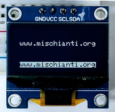
Write text
Here a simple sketch that write a text on screen on specified position.
#include <Wire.h>
#include <Adafruit_GFX.h>
#include <Adafruit_SSD1306.h>

#define SCREEN_WIDTH 128 // OLED display width, in pixels
#define SCREEN_HEIGHT 64 // OLED display height, in pixels

// Declaration for an SSD1306 display connected to I2C (SDA, SCL pins)
#define OLED_RESET     -1 // Reset pin # (or -1 if sharing Arduino reset pin)
Adafruit_SSD1306 display(SCREEN_WIDTH, SCREEN_HEIGHT, &Wire, OLED_RESET);

void setup() {
  Serial.begin(115200);

  delay(2000);
  Serial.println(F("Starting!"));

  // SSD1306_SWITCHCAPVCC = generate display voltage from 3.3V internally
  if(!display.begin(SSD1306_SWITCHCAPVCC, 0x3C)) {
    Serial.println(F("SSD1306 allocation failed"));
    for(;;); // Don't proceed, loop forever
  }
  Serial.println(F("Initialized!"));

  // Show initial display buffer contents on the screen --
  // the library initializes this with an Adafruit splash screen.
  display.display();
  delay(2000); // Pause for 2 seconds

  // Clear the buffer
  display.clearDisplay();
  // Refresh (apply command)
  display.display();

  // Set color of the text
  display.setTextColor(SSD1306_WHITE);
  // Set position of cursor
  display.setCursor(10, 20);
  // Set text size multiplier (x1 standard size)
  display.setTextSize(1);
  // print text like Serial
  display.print(F("www.mischianti.org"));

  display.setCursor(10, 50);
  // Set color of the text and color of the background
  display.setTextColor(SSD1306_BLACK, SSD1306_WHITE);
  display.setTextSize(1);
  display.print(F("www.mischianti.org"));

  // Refresh (apply command)
  display.display();
}

void loop() {
}
The result is
Draw pixels and lines
Now we are going to draw a single pixel and a line.
#include <Wire.h>
#include <Adafruit_GFX.h>
#include <Adafruit_SSD1306.h>

#define SCREEN_WIDTH 128 // OLED display width, in pixels
#define SCREEN_HEIGHT 64 // OLED display height, in pixels

// Declaration for an SSD1306 display connected to I2C (SDA, SCL pins)
#define OLED_RESET     -1 // Reset pin # (or -1 if sharing Arduino reset pin)
Adafruit_SSD1306 display(SCREEN_WIDTH, SCREEN_HEIGHT, &Wire, OLED_RESET);

void setup() {
  Serial.begin(115200);

  delay(2000);
  Serial.println(F("Starting!"));

  // SSD1306_SWITCHCAPVCC = generate display voltage from 3.3V internally
  if(!display.begin(SSD1306_SWITCHCAPVCC, 0x3C)) {
    Serial.println(F("SSD1306 allocation failed"));
    for(;;); // Don't proceed, loop forever
  }
  Serial.println(F("Initialized!"));

  // Show initial display buffer contents on the screen --
  // the library initializes this with an Adafruit splash screen.
  display.display();
  delay(2000); // Pause for 2 seconds

  // Clear the buffer
  display.clearDisplay();
  // Refresh (apply command)
  display.display();

  // Draw a single pixel
  display.drawPixel(10, 10, SSD1306_WHITE);

  // Draw line
  display.drawLine(10, 35, 114, 54, WHITE);

  // Refresh (apply command)
  display.display();
}

void loop() {
}
And the result:
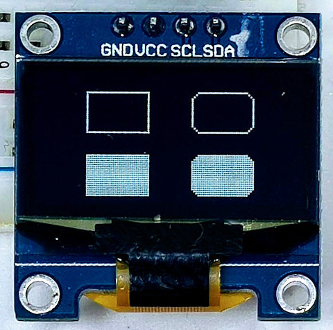
Draw normal, rounded rectangles and squares
Here the sketch.
#include <Wire.h>
#include <Adafruit_GFX.h>
#include <Adafruit_SSD1306.h>

#define SCREEN_WIDTH 128 // OLED display width, in pixels
#define SCREEN_HEIGHT 64 // OLED display height, in pixels

// Declaration for an SSD1306 display connected to I2C (SDA, SCL pins)
#define OLED_RESET     -1 // Reset pin # (or -1 if sharing Arduino reset pin)
Adafruit_SSD1306 display(SCREEN_WIDTH, SCREEN_HEIGHT, &Wire, OLED_RESET);

void setup() {
  Serial.begin(115200);

  delay(2000);
  Serial.println(F("Starting!"));

  // SSD1306_SWITCHCAPVCC = generate display voltage from 3.3V internally
  if(!display.begin(SSD1306_SWITCHCAPVCC, 0x3C)) {
    Serial.println(F("SSD1306 allocation failed"));
    for(;;); // Don't proceed, loop forever
  }
  Serial.println(F("Initialized!"));

  // Show initial display buffer contents on the screen --
  // the library initializes this with an Adafruit splash screen.
  display.display();
  delay(2000); // Pause for 2 seconds

  // Clear the buffer
  display.clearDisplay();
  // Refresh (apply command)
  display.display();

  // Draw a rectangle perimeter
  display.drawRect(25, 10, 30, 20, WHITE);

  // Draw a filled rectangle
  display.fillRect(25, 40, 30, 20, WHITE);

  // Draw a round rectangle perimeter
  display.drawRoundRect(75, 10, 30, 20, 5, WHITE);

  // Draw a round rectangle perimeter
  display.fillRoundRect(75, 40, 30, 20, 5, WHITE);

  // Refresh (apply command)
  display.display();
}

void loop() {
}
And here the result.
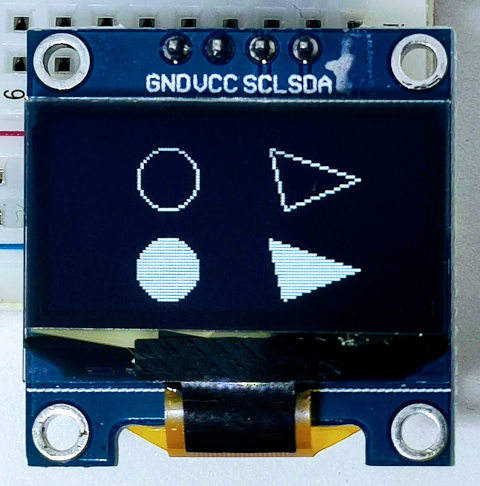
Draw circle and triangle
The last shapes is circle and triangle, here the sketch.
#include <Wire.h>
#include <Adafruit_GFX.h>
#include <Adafruit_SSD1306.h>

#define SCREEN_WIDTH 128 // OLED display width, in pixels
#define SCREEN_HEIGHT 64 // OLED display height, in pixels

// Declaration for an SSD1306 display connected to I2C (SDA, SCL pins)
#define OLED_RESET     -1 // Reset pin # (or -1 if sharing Arduino reset pin)
Adafruit_SSD1306 display(SCREEN_WIDTH, SCREEN_HEIGHT, &Wire, OLED_RESET);

void setup() {
  Serial.begin(115200);

  delay(2000);
  Serial.println(F("Starting!"));

  // SSD1306_SWITCHCAPVCC = generate display voltage from 3.3V internally
  if(!display.begin(SSD1306_SWITCHCAPVCC, 0x3C)) {
    Serial.println(F("SSD1306 allocation failed"));
    for(;;); // Don't proceed, loop forever
  }
  Serial.println(F("Initialized!"));

  // Show initial display buffer contents on the screen --
  // the library initializes this with an Adafruit splash screen.
  display.display();
  delay(2000); // Pause for 2 seconds

  // Clear the buffer
  display.clearDisplay();
  // Refresh (apply command)
  display.display();

  // Draw a circle perimeter
  display.drawCircle(40, 20, 10, WHITE);

  // Draw a filled circle
  display.fillCircle(40, 50, 10, WHITE);

  // Draw a triangle perimeter
  display.drawTriangle(75, 10, 105, 20, 80, 30, WHITE);

  // Draw a filled triangle
  display.fillTriangle(75, 40, 105, 50, 80, 60, WHITE);

  // Refresh (apply command)
  display.display();
}

void loop() {
}
And here the result.
Thanks
- SDD1306 OLED display: basic usage with esp8266, esp32 and Arduino
- SDD1306 OLED display: images, splash and animations
- SDD1306 and PCF8574: manage multiple device on single i2c with interrupt


Hello,
Followed your great resource for interfacing a ESP32 type board – NodeMCU-32s (https://docs.ai-thinker.com/en/esp32/boards/nodemcu_32s) to an Adafruit 128×64 SSD1306 7-pin OLED Display using SPI
However, the sample script ssd1306_128x64_spi is going through successfully, but the screen remains black/off.
Have wired as follows;
Data/MOSI 23
CLK/SCK 18
CS/SS 5
RST 17
DC 16
GND Ground
VIN 3.3V
My wiring slightly changes from yours, as I have followed the manufacturer advice to use GPIO23 for Data instead of 22
Have installed the relevant libraries;
- Adafruit SSD1306 version 2.5.0
- Adafruit GFX version 1.10.12
– Adafruit BusIO version 1.9.8
I have tried using the following board tools:
– NodeMCU-32S Board
– ESP32 Dev Module
– AI Thinker ESP32-CAM
Any advice on where I’m going wrong would be greatly appreciated.
Hi Arnold,
This is my mistake, I write GPIO22 for MOSI but in the schema I connect GPIO23 that is wrong.
You must use GPIO22 for MOSI. I fix the schema
Bye Renzo