
ESP32-wroom-32, esp32-S: flash, pinout, specs and IDE configuration – 1
Here is another article on esp32; we are going to introduce the basic module, which can be used without a specific developer card. Still, to program it, you need to do some wiring and create an adapter (with the programming card, you will undoubtedly do it first, but you want to put the satisfaction).
You can find the esp32-wroom-32 and esp32-s on ESP32 Dev Kit v1 - TTGO T-Display 1.14 ESP32 - NodeMCU V3 V2 ESP8266 Lolin32 - NodeMCU ESP-32S - WeMos Lolin32 - WeMos Lolin32 mini - ESP32-CAM programmer - ESP32-CAM bundle - ESP32-WROOM-32 - ESP32-S
ESP32 programming board Aliexpress adapter esp8266 esp32
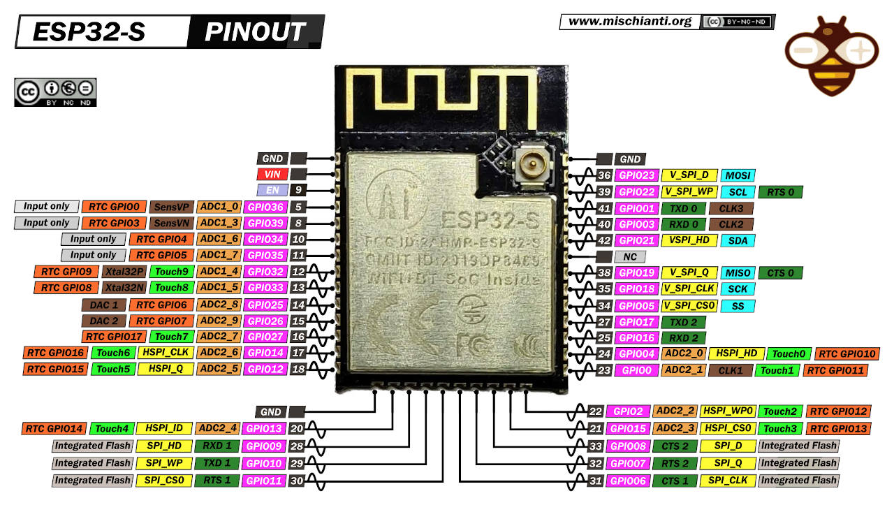
Specs and hight resolution pinout image
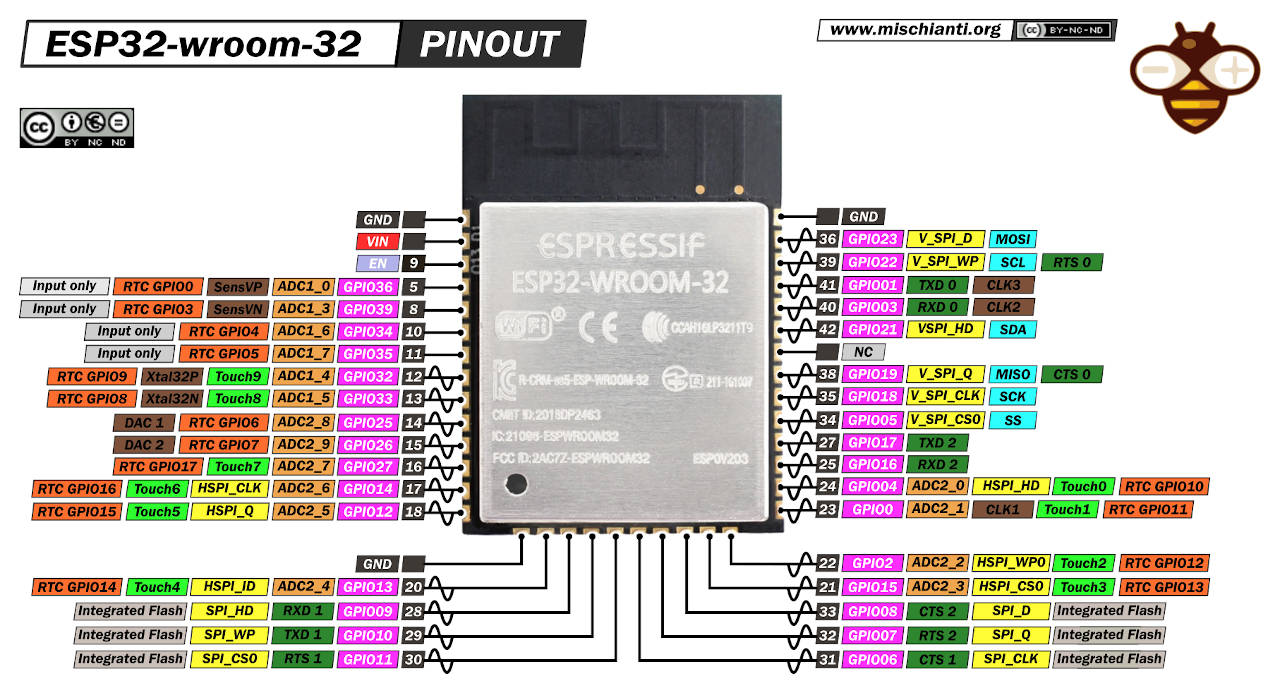
Specs and hight resolution pinout image
Specs
- CPU and Memory
- Xtensa® Dual-Core 32-bit LX6 microprocessors, up to 600 DMIPS
- 448 KByte ROM
- 520 KByte SRAM
- 16 KByte SRAM in RTC
- QSPI Flash/SRAM, up to 4 x 16 MBytes
- Power supply: 2.2 V to 3.6 V
- Clocks and Timers
- Internal 8 MHz oscillator with calibration
- Internal RC oscillator with calibration
- External 2 MHz to 40 MHz crystal oscillator
- External 32 kHz crystal oscillator for RTC with calibration
- Two timer groups, including 2 x 64-bit timers and 1 x main watchdog in each group
- RTC timer with sub-second accuracy
- RTC watchdog
- Advanced Peripheral Interfaces
- 12-bit SAR ADC up to 18 channels
- 2 × 8-bit D/A converters
- 10 × touch sensors
- Temperature sensor
- 4 × SPI
- 2 × I2S
- 2 × I2C
- 3 × UART
- 1 host (SD/eMMC/SDIO)
- 1 slave (SDIO/SPI)
- Ethernet MAC interface with dedicated DMA and IEEE 1588 support
- CAN 2.0
- IR (TX/RX)
- Motor PWM
- LED PWM up to 16 channels
- Hall sensor
- Ultra low power analog pre-amplifier
- Operating Temperature Range: -40 ° C to + 85 ° C
- Package size: 18mm x 25mm x 3mm
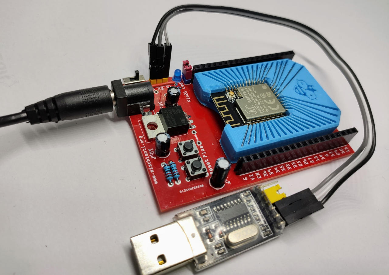
3D printed adapter
A good and fast solution is to print one adapter. Exists a lot of adapters, but I think this is a good choice.
Socket for esp32-wroom-32 V base
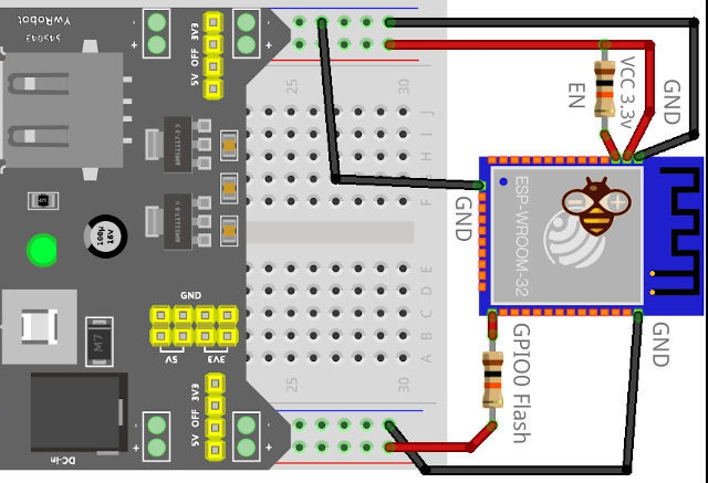
Wiring
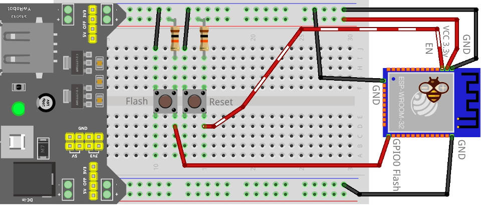
There is some connection to do to use the board correctly, first, we must power and pull up and pull down some pins.
Normal start
Here is the startup configuration: you enable the device (EN pull-up), prevent RESET, and pull up GPIO0 or FLASH fin to prevent that from entering in programming mode.
- EN and GPIO0 need to be pulled high using a 10K resistor;
- then we must power the board with 3.3v and more than 600mA of stable current.
Enter flash mode
Now to put in boot mode you must add 2 button, one to reset the device (put to ground EN), and one to send LOW signal to GPIO0.
Then EN and GPIO0 pull up, and you will connect a button that puts the pin to GND on click like the diagram.
To enter boot mode, you must:
- Hold down the FLASH button;
- Press and release the RST button;
- Release the FLASH button.
Programming with FTDI (USB to Serial converter)
To program the device with this system, it is possible to use an FTDI converter, and there are several types, one that transmits and receives only and one that also supplies a selectable supply voltage.
You can find some kind of FTDI on USB to TTL CH340G - USB to TTL FT232RL
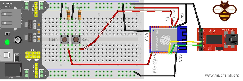
Now you must share the Ground pin and put RX of FTDI to TX of esp and TX to RX.
With the 3d printed adapter, the wiring becomes:
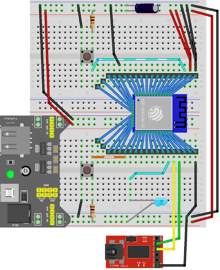
Here is the photo of the result on the breadboard.
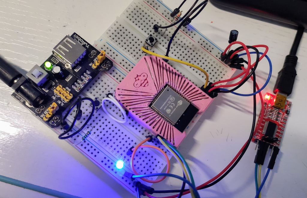
I added a led to pin 21 to check the pin output.
| Mode | GPIO0 |
|---|---|
| UART | High |
| Flash Boot | Low |
Configure IDE
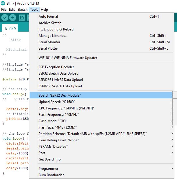
In the Arduino IDE, you must install the esp32 environment. Refer to “ESP32: pinout, specs and Arduino IDE configuration“, then you must configure the correct board information, now I use an esp32-wroom-32 and I set:
- Board: ESP32 Dev Module
- Flash Frequency: 40MHz
- Upload Speed: 921600 (115200 is more secure)
- CPU Frequency: 240 MHz
- Flash Size: 4MB
Upload a simple blink sketch
Now you must only:
- Hold down the FLASH button;
- Press and release the RST button;
- Release the FLASH button;
- Start the upload of this sketch;
/*
    Blink

  Mischainti Renzo www.mischianti.org
*/

//#include "soc/soc.h"
//#include "soc/rtc_cntl_reg.h"

#define LED_PIN 21 // I add the led to the GPIO21

// the setup function runs once when you press reset or power the board
void setup() {
//    WRITE_PERI_REG(RTC_CNTL_BROWN_OUT_REG, 0); //disable brownout detector

  Serial.begin(115200);
  // initialize digital pin LED_PIN as an output.
  pinMode(LED_PIN, OUTPUT);
}

// the loop function runs over and over again forever
void loop() {
  digitalWrite(LED_PIN, HIGH);   // turn the LED on (HIGH is the voltage level)
  Serial.println("HIGH");
  delay(1000);                       // wait for a second
  digitalWrite(LED_PIN, LOW);    // turn the LED off by making the voltage LOW
  Serial.println("LOW");
  delay(1000);                       // wait for a second
}
And here the serial monitor result.
Connect to serial port COM16 at 115200
LOW
HIGH
LOW
HIGH
LOW
HIGH
LOW
HIGH
LOW
HIGH
esp32 programming board PCB
I share the PCB used by me to program esp32 with the 3D-printed socket. Here is the article “ESP32-wroom-32 ESP32-S programming board and breadboard adapter“.
Thanks
- ESP32: pinout, specs and Arduino IDE configuration
- ESP32: integrated SPIFFS Filesystem
- ESP32: manage multiple Serial and logging
- ESP32 practical power saving
- ESP32 practical power saving: manage WiFi and CPU
- ESP32 practical power saving: modem and light sleep
- ESP32 practical power saving: deep sleep and hibernation
- ESP32 practical power saving: preserve data, timer and touch wake up
- ESP32 practical power saving: external and ULP wake up
- ESP32 practical power saving: UART and GPIO wake up
- ESP32: integrated LittleFS FileSystem
- ESP32: integrated FFat (Fat/exFAT) FileSystem
- ESP32-wroom-32
- ESP32-CAM
- ESP32: use ethernet w5500 with plain (HTTP) and SSL (HTTPS)
- ESP32: use ethernet enc28j60 with plain (HTTP) and SSL (HTTPS)
- How to use SD card with esp32
- esp32 and esp8266: FAT filesystem on external SPI flash memory
- Firmware and OTA update management
- Firmware management
- OTA update with Arduino IDE
- OTA update with Web Browser
- Self OTA uptate from HTTP server
- Non-standard Firmware update
- Integrating LAN8720 with ESP32 for Ethernet Connectivity with plain (HTTP) and SSL (HTTPS)
- Connecting the EByte E70 to ESP32 c3/s3 devices and a simple sketch example
- ESP32-C3: pinout, specs and Arduino IDE configuration


Hi, one question: in Programming with Ftdi you show two pictures, one does not have a capacitor while in the other 3D printed you show a capacitor. Are they different? What is the purpose of this capacitor?
Hi Riaz,
you are right, but the purpose of the capacitor is to prevent noise on the power supply, so you probably don’t need It even if It can prevent some issues on upload; it’s a good thing to add.
Bye Renzo