ABB Aurora Web Inverter Monitor (WIM): upload the sketch and front end – 9
I’m going to add this section because I realized that the sketch is quite complex and a little guide can help in the operation.
Install Optional Tools
The use of these tools is optional as they are useful, but not required.
Git
Git 2.0 or greater is required only if you want to clone the source code locally. At a command line, you can verify if git is installed by running the command:
git --version
If it is not properly installed or is not a version greater than 2.0, visit https://git-scm.com/downloads to download and install a version for your platform.
Get the Source Code via Git
If you have git installed on your workstation, you can use the following instructions to pull the source code into your working directory.
- From the command-line, navigate into the working directory on your desktop:
arduino-projects - Run the following command to pull the source code to a working directory:
git clone https://github.com/xreef/Aurora_Web_Invert_Monitor.git
Get the Source Code via Download
If you do not have git installed, download and unzip the zipped contents of the sample from https://github.com/xreef/Aurora_Web_Invert_Monitor/archive/master.zip into your desktop working directory: Aurora_Web_Invert_Monitor.
Libraries
Now you need to install a long list of library
- ArduinoJson
You can find information about this library on “Manage JSON file with Arduino, esp32 and esp8266“ - ArduinoThread
You can find in the Arduino IDE library manager or on GitHub - ABB_Aurora_Solar_Inverter_Library
You can find information about this library on “Manage JSON file with Arduino, esp32 and esp8266“ - DNSServer
esp8266 core builtin. - EMailSender
You can find information about this library on “Send email with attachments (EMailSender v2.x library): esp32 and esp8266” (Disable attachments to save mem) - ESP8266mDNS
esp8266 core builtin. - ESP8266SdFat
esp8266 core builtin, pay attention if you have SdFat library, remove It. - ESP8266WiFi
esp8266 core builtin. - Hash
esp8266 core builtin. - NTPClient
- TimeLib
- Timezone
You can find information about this 3 libraries on “Network Time Protocol (NTP), Timezone and Daylight saving time (DST) with esp8266, esp32 or Arduino“ - SD
You can find information about this library on “How to use SD card with esp8266, esp32 and Arduino“ - SDFS
esp8266 core builtin. - SPI
esp8266 core builtin. - ESP8266WebServer
You can find information about this library on “Web Server with esp8266 and esp32“ - WebSockets
You can find information about this library on “WebSocket on Arduino, esp8266 and esp32“ - WiFiManager
You can find information about this library on “How to manage dynamic WIFI configuration on esp8266 or esp32“ - Wire
Now after you had upload the code you must upload the data folder, to do that you can follow this guide “WeMos D1 mini (esp8266), integrated SPIFFS Filesystem“.
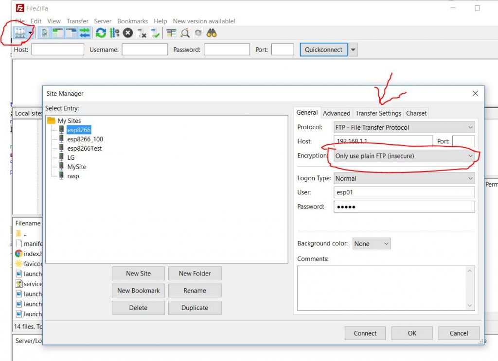
To upload the data you can also uncomment the ftp server define
// Uncomment to enable server ftp.
#define SERVER_FTP
if you do that you can upload web part data, the user is aurora and password aurora, pay attention to your client configuration, follow this tutorial “FTP server on esp8266 and esp32“.
For the NTP management I use the european server, and It’s synchronized one time per hour, if you want change that the line to modify is this
NTPClient timeClient(ntpUDP, "europe.pool.ntp.org", 0*60*60, 60*60*1000);
To work you need to connect the SD adapter with relative SD.
Upload precompiled firmware (reccomended)
To simplify the process I add the precompiled firmware, you can find 4 files:
Firmware
- Aurora_Web_Inverter_Monitor_DEBUG_FTP.d1_mini.bin: Firmware with FTP server to upload filesystem and DEBUG active
- Aurora_Web_Inverter_Monitor_DEBUG.d1_mini.bin: Firmware with DEBUG active
- Aurora_Web_Inverter_Monitor.d1_mini.bin: Firmware standard
Filesystem
- Aurora_Web_Inverter_Monitor.spiffs.bin: Filesystem in binary
Upload from command prompt
upload.py or esptool.py
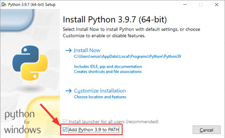
First we look that the core component of esp8266 core need python installed, and when install It remember to add to path (for windows)
In your installation of Arduino IDE you can find upload.py file that is the same of esptool.py.
You can install only esptool.py for python with a simple command
pip install esptool
or you can download from here the compiled version, remember to add the executable to path.
Then if you launch esptool on your cmd you have this information
D:\Projects\Arduino\sloeber-workspace-OTA\keys>esptool
esptool.py v3.1
usage: esptool [-h]
               [--chip {auto,esp8266,esp32,esp32s2,esp32s3beta2,esp32s3beta3,esp32c3,esp32c6beta}]
               [--port PORT] [--baud BAUD]
               [--before {default_reset,usb_reset,no_reset,no_reset_no_sync}]
               [--after {hard_reset,soft_reset,no_reset,no_reset_stub}]
               [--no-stub] [--trace] [--override-vddsdio [{1.8V,1.9V,OFF}]]
               [--connect-attempts CONNECT_ATTEMPTS]
               {load_ram,dump_mem,read_mem,write_mem,write_flash,run,image_info,make_image,elf2image,read_mac,chip_id,flash_id,read_flash_status,write_flash_status,read_flash,verify_flash,erase_flash,erase_region,merge_bin,version,get_security_info}
               ...

esptool.py v3.1 - ESP8266 ROM Bootloader Utility

positional arguments:
  {load_ram,dump_mem,read_mem,write_mem,write_flash,run,image_info,make_image,elf2image,read_mac,chip_id,flash_id,read_flash_status,write_flash_status,read_flash,verify_flash,erase_flash,erase_region,merge_bin,version,get_security_info}
                        Run esptool {command} -h for additional help
    load_ram            Download an image to RAM and execute
    dump_mem            Dump arbitrary memory to disk
    read_mem            Read arbitrary memory location
    write_mem           Read-modify-write to arbitrary memory location
    write_flash         Write a binary blob to flash
    run                 Run application code in flash
    image_info          Dump headers from an application image
    make_image          Create an application image from binary files
    elf2image           Create an application image from ELF file
    read_mac            Read MAC address from OTP ROM
    chip_id             Read Chip ID from OTP ROM
    flash_id            Read SPI flash manufacturer and device ID
    read_flash_status   Read SPI flash status register
    write_flash_status  Write SPI flash status register
    read_flash          Read SPI flash content
    verify_flash        Verify a binary blob against flash
    erase_flash         Perform Chip Erase on SPI flash
    erase_region        Erase a region of the flash
    merge_bin           Merge multiple raw binary files into a single file for
                        later flashing
    version             Print esptool version
    get_security_info   Get some security-related data

optional arguments:
  -h, --help            show this help message and exit
  --chip {auto,esp8266,esp32,esp32s2,esp32s3beta2,esp32s3beta3,esp32c3,esp32c6beta}, -c {auto,esp8266,esp32,esp32s2,esp32s3beta2,esp32s3beta3,esp32c3,esp32c6beta}
                        Target chip type
  --port PORT, -p PORT  Serial port device
  --baud BAUD, -b BAUD  Serial port baud rate used when flashing/reading
  --before {default_reset,usb_reset,no_reset,no_reset_no_sync}
                        What to do before connecting to the chip
  --after {hard_reset,soft_reset,no_reset,no_reset_stub}, -a {hard_reset,soft_reset,no_reset,no_reset_stub}
                        What to do after esptool.py is finished
  --no-stub             Disable launching the flasher stub, only talk to ROM
                        bootloader. Some features will not be available.
  --trace, -t           Enable trace-level output of esptool.py interactions.
  --override-vddsdio [{1.8V,1.9V,OFF}]
                        Override ESP32 VDDSDIO internal voltage regulator (use
                        with care)
  --connect-attempts CONNECT_ATTEMPTS
                        Number of attempts to connect, negative or 0 for
                        infinite. Default: 7.
Command line parameters
Now we can better understand the parameter:
--chip esp8266: here we are going to select the correct chip;--port COM17: we set the port;--baud 921600: here we have the transfer speed;erase_flash: perform Chip Erase on SPI flash (clear all information);--before default_reset: pre-upload operation;--after hard_reset: post-upload operation;write_flash: write a binary blob to flash;0x0<binary file>: write to address the file.
To upload you can try to use esptool with these command:
Firmware
esptool --port /dev/COM24 write_flash -fm dio 0x00000 Aurora_Web_Inverter_Monitor.d1_mini.bin
Filesystem
esptool --port /dev/COM24 write_flash -fm dio 0x10000 Aurora_Web_Inverter_Monitor.spiffs.bin
Upload with GUI tool
You can use a GUI tool from espressif to simplify the process, Espressif Download Tool can download from here.
With the gui we must simply set the correct files and address.
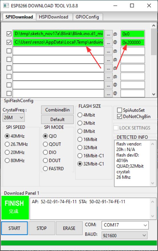
You must select a firmware version and set address 0x0, and filesystem with address 0x200000, select correct port and click to start.
Memory problem in sending emails
If you encounter problems sending emails, you need to install everything with version 2.4.2 of the esp8266 core environment.
The library list changes slightly due to the renewed handling of SD cards.
ABB_Aurora_Solar_Inverter_Library:comment//#define ADD_SOFTWARE_SERIALWireSDSPIArduinoThreadESP8266WiFiTimeLibNTPClientESP8266mDNSESP8266WebServerArduinoJsonWiFiManagerDNSServerEMailSender:you need to set#define DEFAULT_EMAIL_NETWORK_TYPE_ESP8266 NETWORK_ESP8266_242TimezoneWebSocketsHash
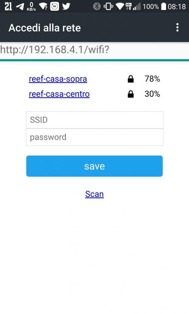
First time start
First remember to configure the WiFi connection, read the relative article “ABB (Power One) Aurora Web Inverter Monitor (WIM): WIFI configuration and REST Server“.
When you have configured the WiFi It’s better (but not needed) if you connect an USB to TTL on Serial1, check how to do that on “ABB Aurora web inverter centraline (WIC): debug and notification“, remember to uncomment the debug define
// Uncomment to enable printing out nice debug messages.
#define AURORA_SERVER_DEBUG
From the Serial1 output you can grab the ip address to connect the first time with the browser.
After the connection go to configuration section and set a Static IP
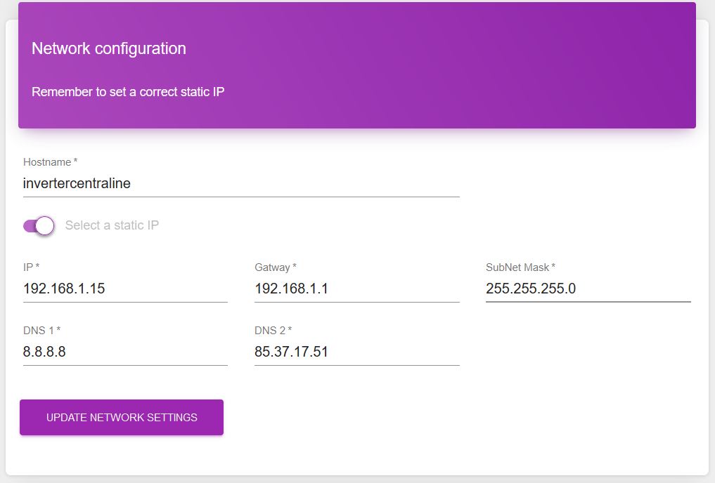
Then set the correct DST (or if not defined set GTM) and admin email.

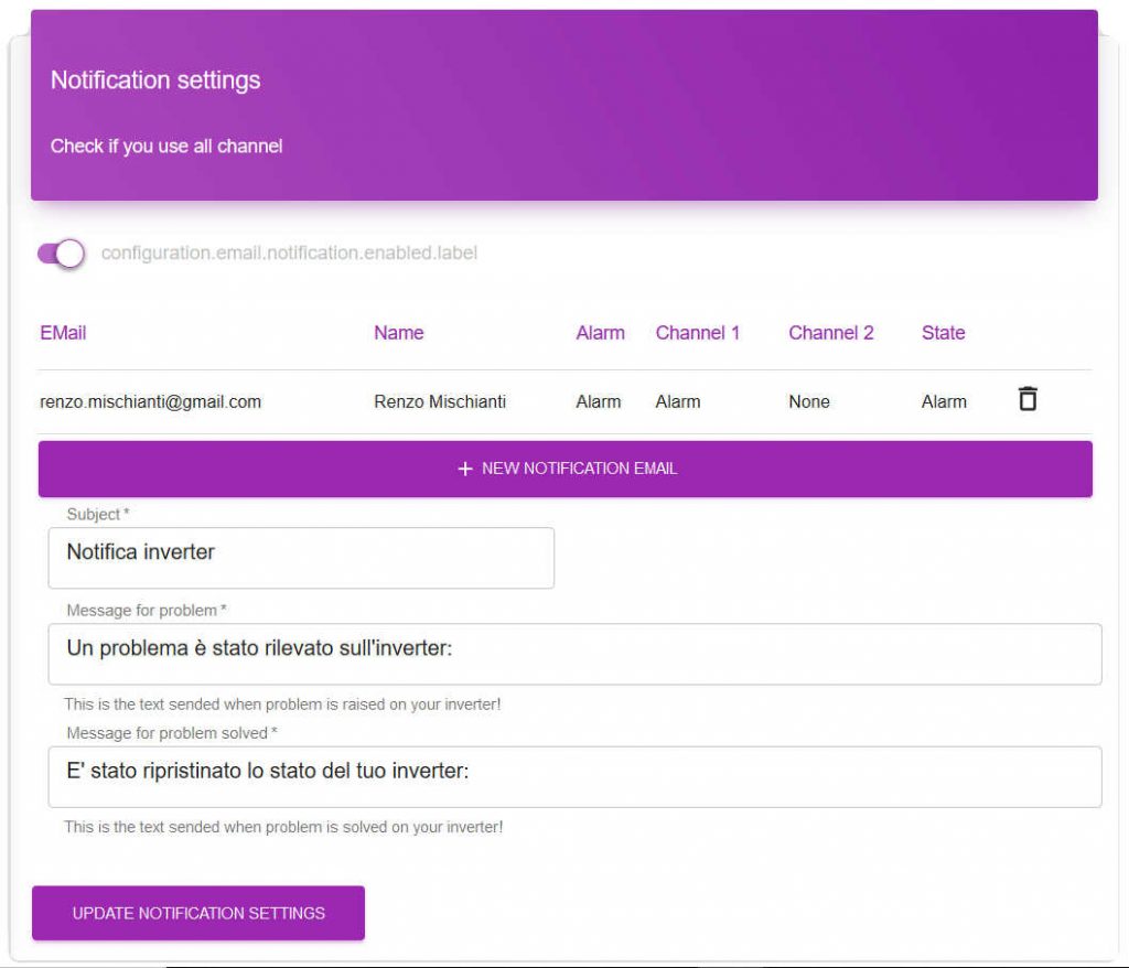
Next step (very important) configure the notification of the Inverter error, this features can save you money loss if something goes wrong.
Now all is configured, wait a day that the WIC store some data then return to the web interface and check the charts.
Thanks
Remember for all information or issue use the forum.
- ABB Aurora Web Inverter Monitor (WIM): project introduction
- ABB Aurora Web Inverter Monitor (WIM): wiring Arduino to RS-485
- ABB Aurora Web Inverter Monitor (WIM): storage devices
- ABB Aurora Web Inverter Monitor (WIM): debug and notification
- ABB Aurora Web Inverter Monitor (WIM): set time and UPS
- ABB Aurora Web Inverter Monitor (WIM): WIFI configuration and REST Server
- ABB Aurora Web Inverter Monitor (WIM): WebSocket and Web Server
- ABB Aurora Web Inverter Monitor (WIM): Wiring and PCB soldering
- ABB Aurora Web Inverter Monitor (WIM): upload the sketch and front end
- ABB Aurora web inverter Monitor (WIM): 3D printed case to complete project
- ABB Aurora web inverter monitor (WIM): repair E013 error
GitHub repository with all code BE and FE transpiled