
ABB Aurora Web Inverter Monitor (WIM): wiring Arduino to RS-485 – 2
I created a library that implement the full communication protocolo of ABB (ex PowerOne now Fimer) Aurora Inverter and It need to connect the inverter via RS485.
You can find the library here “ABB Aurora PV inverter library for Arduino, esp8266 and esp32“.
Inverter hardware
First you must find RS485 interface of your inverter, in mine I must remove frontal panel
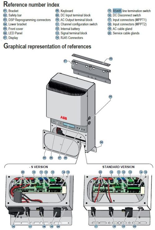
Than check the RS485 interface position and get positive and negative connector.
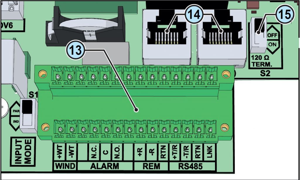
| Ref. inverter | Ref. manual | Description |
| WIND | 13 | Connection of the Tachometer signal (WIND) |
| ALARM | 13 | Connection to the multi-function relay (ALARM) |
| REM | 13 | Connection to the remote ON/OFF (REM) |
| RS485 | 13 | Connection of the RS485 (PC) line (RS485) |
| J24 – RS485 (A) | 14 | Connection of the RS485 (PC) line on RJ45 connector |
| J25 – RS485 (B) | 14 | Connection of the RS485 (PC) line on RJ45 connector |
| S2 | 15 | RS485 line (PC) termination resistance selector switch |
So connect to +T and -T and extract the wire and we are going to check RS-485 interface of your inverter

You can connect the conductors using the terminal connectors 13 (+T/R, -T/R, LNK and RTN) the LNK also.
You must also put to on il Line terminal switch.
If you want use ethernet connector you must follow this schema.
| Pin No. | Function |
| 3 | +T/R |
| 4 | +R |
| 5 | -T/R |
| 7 | RTN |
| 1, 2, 6, 8 | not used |

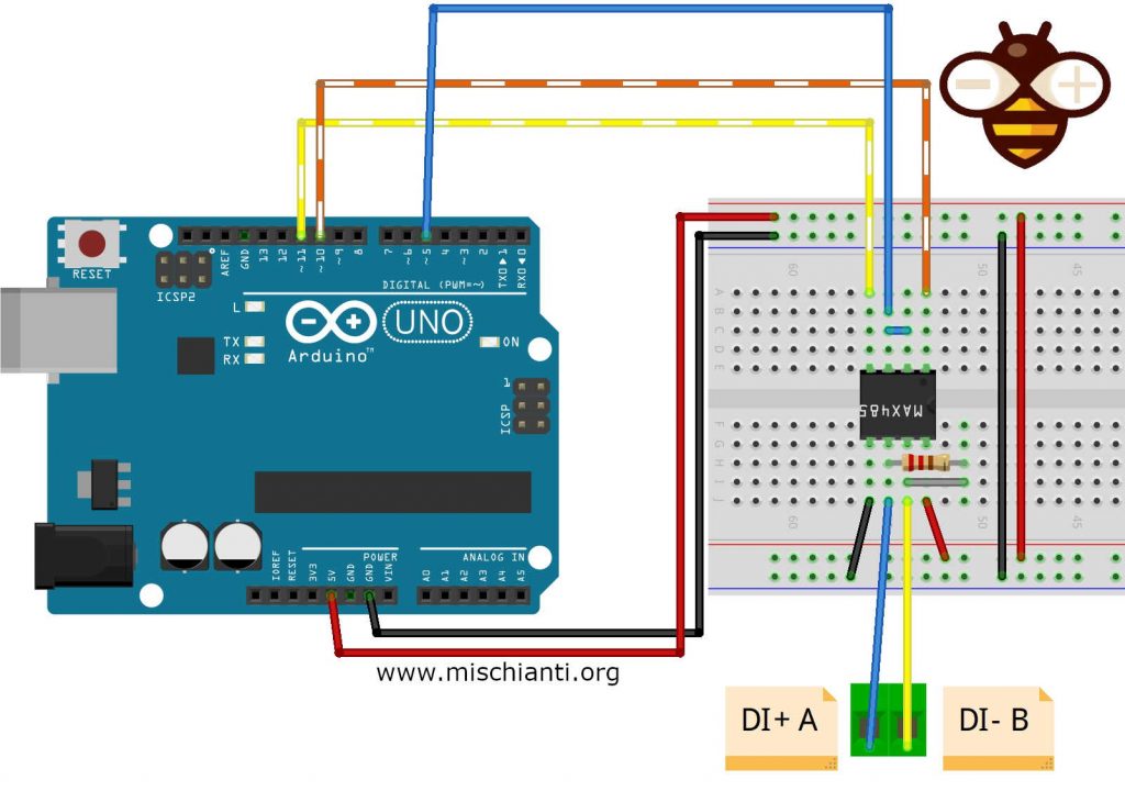
| MAX485 | Inverter |
|---|---|
| GND | RTN |
| A | +T |
| B | -T |
ABB Aurora protocol (refer library for more detail)
Here the base information of RS485 ABB Aurora communication Protocol.
The communication between Host and processor works via a Serial Interface RS485 or RS232.
Configuration parameters in both cases are:
- 19200 baud (default value)
- 1 stop bit
- no parity
The communication protocol uses fixed length transmission messages (8Bytes + 2Bytes for Checksum) structured as follows:
| 0 | 1 | 2 | 3 | 4 | 5 | 6 | 7 | 8 | 9 |
| Address | Command | B2 | B3 | B4 | B5 | B6 | B7 | CRC_L | CRC_H |
The structure of the answer has also fixed length (6 Bytes + 2 Bytes for Checksum) :
| 0 | 1 | 2 | 3 | 4 | 5 | 6 | 7 |
| Transmission State | Global State | B2 | B3 | B4 | B5 | CRC_L | CRC_H |
Transmission State:
Coded as follows:
0 = Everything is OK.
51 = Command is not implemented
52 = Variable does not exist
53 = Variable value is out of range
54 = EEprom not accessible
55 = Not Toggled Service Mode
56 = Can not send the command to internal micro
57 = Command not Executed
58 = The variable is not available, retry
Global State:
It shows the state of the addressed device, the details are specified in the description of the commands.
Arduino UNO and MAX485
For this preliminary test connection test I use an Arduino UNO and a MAX485 IC, if you prefer can buy a module.
You can find IC on AliExpress
You can find module on AliExpressAliExpress
You can find WeMos D1 mini on WeMos D1 mini - NodeMCU V2 V2.1 V3 - esp01 - esp01 programmer
Here the simple connection schema, the resistor must be 120Ω, i use 150Ω.
If you want try directly with esp8266 in the article dedicated to the RS-485 communication you can find more information, but when arrive the moment I explain good esp8266 connection also.
I create a library derived from a project that you can find in the web created by drhack, It’s a fantastic works (thanks to drhack) but I find It quite difficult to use, with specific hardware and not so reusable.
So I try to standardize the library and made It simple (the people that use my library know that “simplify first” It’s my motto.
Library
You can find my library explained here “ABB Aurora PV inverter library for Arduino, esp8266 and esp32“.
Packet
As you can see in the packet description
| 0 | 1 | 2 | 3 | 4 | 5 | 6 | 7 | 8 | 9 |
| Address | Command | B2 | B3 | B4 | B5 | B6 | B7 | CRC_L | CRC_H |
you must specify an address, that address normally is 2, but you must check It in your inverter menu.
You can create a chain of inverters that communicate via RS485. An address can be chosen from 2 to 63. The address on the inverter is set through the display and the pushbutton panel.
To change address go to SETTINGS --> Insert password (default 0000) --> Address.
This menu allows you to set the serial port addresses of the individual inverters connected to the RS485 line.
The addresses that can be assigned are 2 to 63. The UP and DOWN buttons scroll through the numerical scale. ‘AUTO’ selection cannot be used at present.
For “production” module I’m going to use HardwareSerial to optimize the communication and reduce overhead.
/*
 Test Arduino MAX485 Aurora ABB connection
 by Mischianti Renzo <https://mischianti.org>

 https://www.mischianti.org/
*/

#include "Arduino.h"
#include <Aurora.h>
#include <SoftwareSerial.h>
#include <MemoryFree.h>

//SoftwareSerial mySerial(10, 11); // RX, TX
//Aurora inverter = Aurora(2, &Serial1, 5);
Aurora inverter = Aurora(2, 10, 11, 5);

void SerialPrintData(byte *data) {
  for (int i = 0; i < 8; i++) {
    Serial.print((int)data[i]);
    Serial.print(F(" "));
  }
  Serial.println(F(" "));

}

void setup()
{
	Serial.begin(19200);
	inverter.begin();
}

// The loop function is called in an endless loop
void loop()
{
	Serial.print(F("freeMemory(1)="));Serial.println(freeMemory());

	Aurora::DataCumulatedEnergy cumulatedEnergy = inverter.readCumulatedEnergy(CUMULATED_DAILY_ENERGY);
    Serial.println(F("------------------------------------------"));
    Serial.println(F("INVERTER 2"));
    Serial.print(F("          Data ROW = ")); SerialPrintData(inverter.receiveData);
    Serial.print(F("        Read State = ")); Serial.println(cumulatedEnergy.state.readState);
    Serial.print(F("Transmission State = ")); Serial.println(cumulatedEnergy.state.getTransmissionState());
    Serial.print(F("      Global State = ")); Serial.println(cumulatedEnergy.state.getGlobalState());
    Serial.print(F("           Energia = ")); Serial.print(cumulatedEnergy.energy); Serial.println(" Wh");
//    free(&cumulatedEnergy);
    Serial.println(F("------------------------------------------"));


	Aurora::DataLastFourAlarms lastFour = inverter.readLastFourAlarms();

    Serial.println(F("INVERTER 2"));
    Serial.print(F("          Data ROW = "));  SerialPrintData(inverter.receiveData);
	Serial.print(F("        Read State = "));  Serial.println(lastFour.state.readState);
    Serial.print(F("Transmission State = "));  Serial.println(lastFour.state.getTransmissionState());
    Serial.print(F("      Global State = "));  Serial.println(lastFour.state.getGlobalState());
    Serial.print(F("          Alarms 1 = "));  Serial.println(lastFour.getAlarm1State());
    Serial.print(F("          Alarms 2 = "));  Serial.println(lastFour.getAlarm2State());
    Serial.print(F("          Alarms 3 = "));  Serial.println(lastFour.getAlarm3State());
    Serial.print(F("          Alarms 4 = "));  Serial.println(lastFour.getAlarm4State());
//	free(&lastFour);

    Serial.println(F("------------------------------------------"));

    Aurora::DataVersion version = inverter.readVersion();
    Serial.println("INVERTER 2");
    Serial.print(F("          Data ROW = ")); SerialPrintData(inverter.receiveData);
    Serial.print(F("        Read State = ")); Serial.println(version.state.readState);
    Serial.print(F("Transmission State = ")); Serial.println(version.state.getTransmissionState());
    Serial.print(F("      Global State = ")); Serial.println(version.state.getGlobalState());
    Serial.print(F("           Version = ")); Serial.print(version.getModelName().name); Serial.print(F(" ")); Serial.print(version.getIndoorOutdoorAndType()); Serial.print(F(" ")); Serial.print(version.getGridStandard()); Serial.print(F(" ")); Serial.print(version.getTrafoOrNonTrafo()); Serial.print(F(" ")); Serial.println(version.getWindOrPV());
    Serial.println(F("------------------------------------------"));
//	free(&version);

    Aurora::DataConfigStatus configStatus = inverter.readConfig();

    Serial.print(F("          Data ROW = ")); SerialPrintData(inverter.receiveData);
    Serial.print(F("        Read State = ")); Serial.println(configStatus.state.readState);
    Serial.print(F("Transmission State = ")); Serial.println(configStatus.state.getTransmissionState());
    Serial.print(F("      Global State = ")); Serial.println(configStatus.state.getGlobalState());
    Serial.print(F("      config       = ")); Serial.println(configStatus.getConfigStatus());
    Serial.println(F("------------------------------------------"));
//	free(&version);
    Serial.print(F("freeMemory(2)="));Serial.println(freeMemory());

    Aurora::DataTimeCounter timeCounter = inverter.readTimeCounter(CT_TOTAL_RUN);

    Serial.print(F("          Data ROW = ")); SerialPrintData(inverter.receiveData);
    Serial.print(F("        Read State = ")); Serial.println(timeCounter.state.readState);
    Serial.print(F("Transmission State = ")); Serial.println(timeCounter.state.getTransmissionState());
    Serial.print(F("      Global State = ")); Serial.println(timeCounter.state.getGlobalState());
    Serial.print(F("      time in sec  = ")); Serial.println(timeCounter.upTimeInSec);
    Serial.print(F("      time in verb  = ")); Serial.print(timeCounter.getSecondsInDateElements()[0]); Serial.print(F("Y ")); Serial.print(timeCounter.getSecondsInDateElements()[1]); Serial.print(F("D "));Serial.print(timeCounter.getSecondsInDateElements()[2]);Serial.print(F("H "));Serial.print(timeCounter.getSecondsInDateElements()[3]);+Serial.print(F("M "));Serial.print(timeCounter.getSecondsInDateElements()[4]);Serial.println(F("S "));
    Serial.println(F("------------------------------------------"));
//	free(&version);
    Serial.print(F("freeMemory(2)="));Serial.println(freeMemory());

    delay(4000);

}
Thanks
- ABB Aurora Web Inverter Monitor (WIM): project introduction
- ABB Aurora Web Inverter Monitor (WIM): wiring Arduino to RS-485
- ABB Aurora Web Inverter Monitor (WIM): storage devices
- ABB Aurora Web Inverter Monitor (WIM): debug and notification
- ABB Aurora Web Inverter Monitor (WIM): set time and UPS
- ABB Aurora Web Inverter Monitor (WIM): WIFI configuration and REST Server
- ABB Aurora Web Inverter Monitor (WIM): WebSocket and Web Server
- ABB Aurora Web Inverter Monitor (WIM): Wiring and PCB soldering
- ABB Aurora Web Inverter Monitor (WIM): upload the sketch and front end
- ABB Aurora web inverter Monitor (WIM): 3D printed case to complete project
- ABB Aurora web inverter monitor (WIM): repair E013 error
GitHub repository with all code BE and FE transpiled


Hello. Maybe you can add sketch for WeMos D1 mini.
Hi,
you can find It in the relative article.
ABB Aurora PV inverter library for Arduino, esp8266 and esp32
Bye Renzo
I am trying to connect to the Aurora unit as described here but with no success. There is no data comming from RS485. Is there anything else that needs to be set up for arduino to work? I also tried the USB connection but Aurora communicator can read any data (I see data being send over htem but it is all zeroes at 19200). Any ideas how to solve it?
Hi Milan,
if you follow all the steps I explained in the articles, I think there is a problem with the Inverter.
Bye Renzo
My ABB PowerOne has an RJ11 connector for the RS485, do you know the pinout for the RJ11. Also does it matter if the RJ11 is plugged into the in or out socket.
Hi Jason,
sorry mine has only RJ45.
Bye Renzo