
How to interface Arduino, esp8266 or esp32 to RS-485
Hi all, I am doing a project for my inverter centreline, and the first problem to solve is to interface my microcontrollers to the inverter.
The inverter is ABB Aurora and has an interface RS-485. First, I try with Arduino, but I’m going to use an esp8266.
RS-485 work as a broadcast. When you send a message, all devices connected to the wire receive that, so there are a lot of protocols to manage point-to-point communication and broadcast. This article uses normal communication from two devices in a very simple way.
But as you can understand, with a specified protocol, you can control a lot of devices at the same time.
IC or module
Exists IC and module adapt for this type of connection, for Arduino, you can use IC MAX485 or a relative module, for esp8266 and esp32, you must use MAX3485 that works at 3.3v.
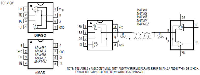
MAX485
You can find the IC on AliExpress
You can find the module on AliExpress
The MAX485 is a low-power transceiver for RS-485 communication. Contain one driver and one receiver.
Key Features
- Low Power Consumption Minimizes Thermal Dissipation, Reducing System Cost
- 120µA to 500µA Quiescent Current
- Shutdown Current of 0.1µA
- Single 5V Supply Voltage
- Integrated Protection Enhances System Robustness
- Short Circuit Current Limited Driver
- Integrated Thermal Shutdown
- Receiver Fail-Safe for Input Open Circuit
- Guarantees Logic High
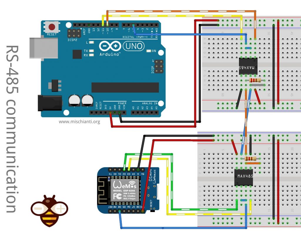
Wiring Arduino UNO
This IC is perfect for working with Arduino or other 5v logic devices, here is the connection schema:
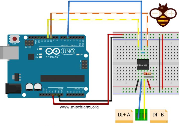
The connection is quite simple, you must connect Pin 5 to DE and -RE so you can activate the transmission and reception of the data. In the schema, I use 10 and 11 pins, respectively as RX and TX of SoftwareSerial, and you must connect to RO DI pins of MAX485, then you must attach 5v and GND to the IC pins. The resistor Rt (from A and B) is 120ohm, but I usually use 104ohm.
When you connect MAX485 to the device, remember that pin A is DI+ and B is DI-.
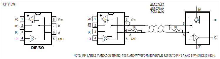
MAX3485
You can find the IC on AliExpress
You can find the module on AliExpressAliExpress
The MAX3485 is 3.3V, a low-power transceiver for RS-485 communication. It contains one driver and one receiver. The MAX3485 transmits at up to 10Mbps.
Drivers are short-circuited current limited and are protected against excessive power dissipation by thermal shutdown circuitry that places the driver outputs into a high-impedance state. The receiver input has a fail-safe feature that guarantees a logic-high output if both inputs are open circuits.
The MAX3485 is designed for half-duplex communication.
Key Features
- Operate from a Single 3.3V Supply-No Charge Pump!
- Interoperable with +5V Logic
- 8ns Max Skew
- 2nA Low-Current Shutdown Mode
- -7V to +12V Common-Mode Input Voltage Range
- Allows up to 32 Transceivers on the Bus
- Full-Duplex and Half-Duplex Versions Available
- Industry Standard 75176 Pinout
- Current-Limiting and Thermal Shutdown for Driver Overload Protection
Wiring esp8266
This IC is perfect for working with esp8266, esp32, or other 3.3v logic devices, here is the connection schema:
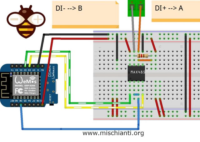
The connection is quite simple, you must connect Pin D0 to DE and -RE so you can activate transmission and reception of the data, in the schema, I use D3 and D2 pins, respectively, as RX and TX of SoftwareSerial and you must connecto to RO DI pins of MAX3485, then you must attach 3.3v and GND to the IC pins. The resistor Rt (from A and B) is 120ohm, but I usually use 104ohm.
When you connect MAX3485 to the device, remember that pin A is DI+ and B is DI-.
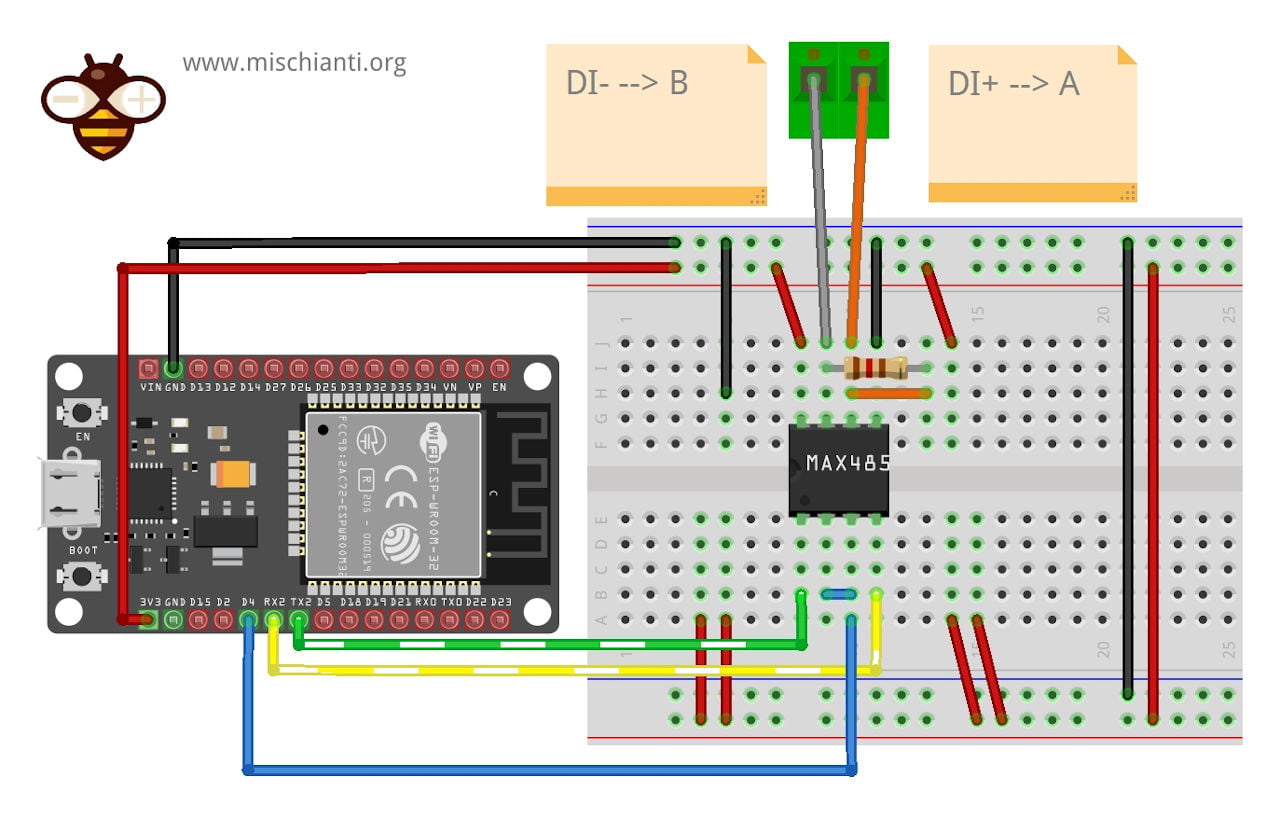
Wiring esp32
Similar connection for ESP32, but we are going to use Serial1 interface not software serial.
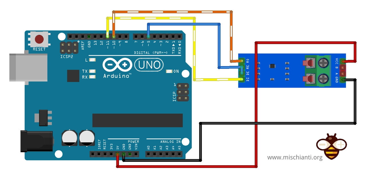
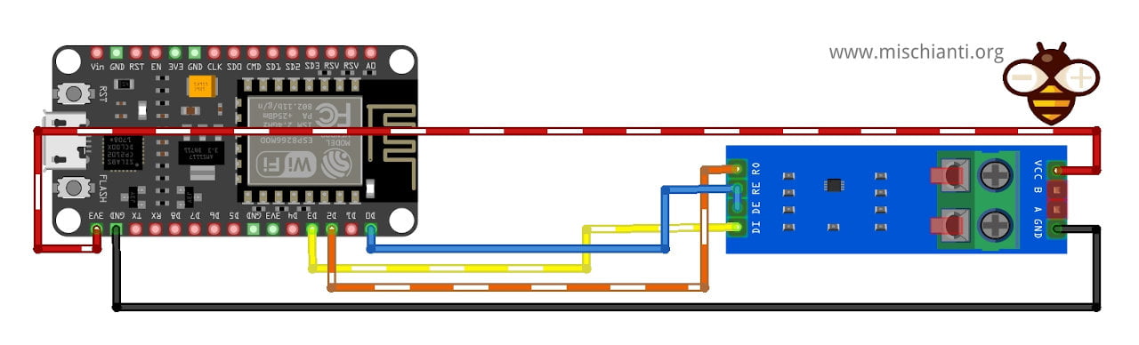
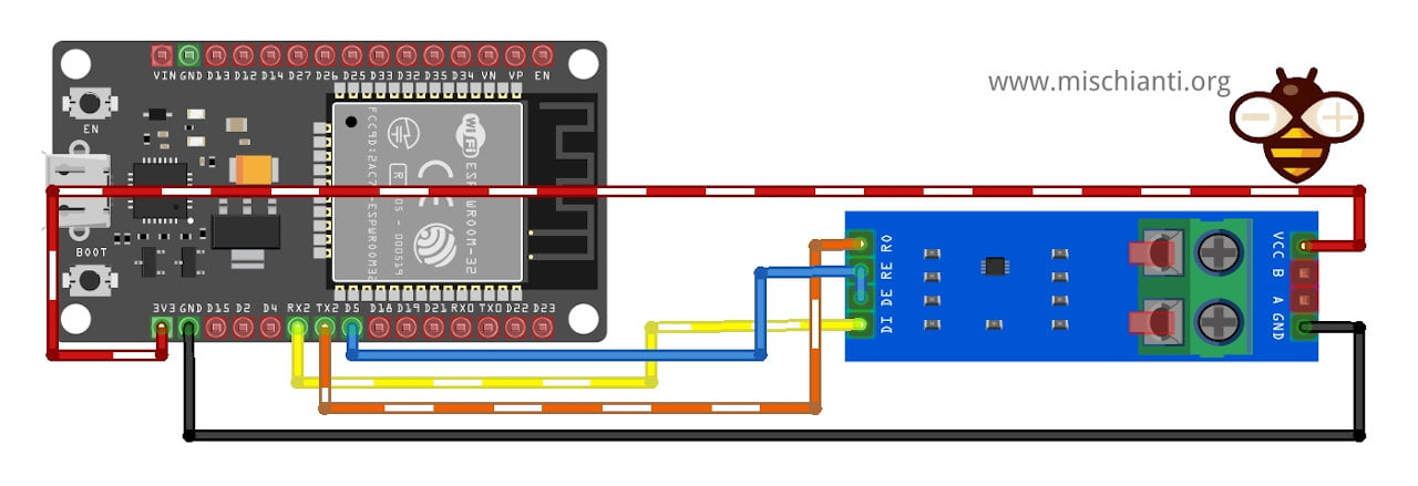
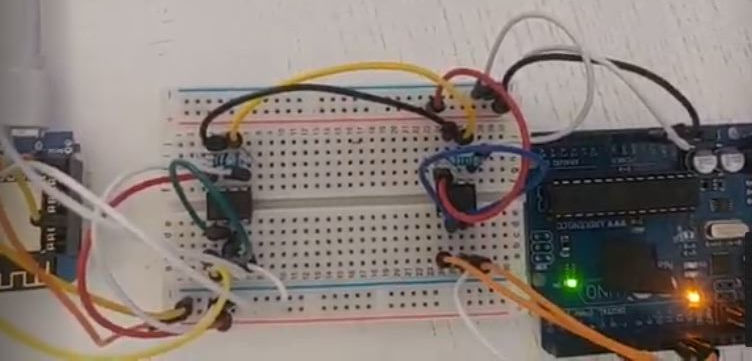
And here is the module connection.
How to
When you have a datasheet of the device to interconnect, the usage is quite simple, you use the serial communication interface of your microcontroller to send and receive data.
And here 2 simple sketch.
Sketch
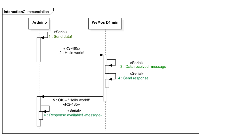
First Arduino send a message “Hello World!” and wait response.
#include "Arduino.h"

#include <SoftwareSerial.h>
#define RXPin        10  // Serial Receive pin
#define TXPin        11  // Serial Transmit pin

//RS485 control
#define SERIAL_COMMUNICATION_CONTROL_PIN 5 // Transmission set pin
#define RS485_TX_PIN_VALUE HIGH
#define RS485_RX_PIN_VALUE LOW

SoftwareSerial RS485Serial(RXPin, TXPin); // RX, TX

int byteSend;

void setup()  {
  Serial.begin(19200);

  pinMode(SERIAL_COMMUNICATION_CONTROL_PIN, OUTPUT);
  digitalWrite(SERIAL_COMMUNICATION_CONTROL_PIN, RS485_RX_PIN_VALUE);
  RS485Serial.begin(19200);   // set the data rate

  delay(500);

  digitalWrite(SERIAL_COMMUNICATION_CONTROL_PIN, RS485_TX_PIN_VALUE); // Now trasmit
  Serial.println("Send data!");
  RS485Serial.print("Hello world!"); // Send message
}

void loop() {
	  digitalWrite(SERIAL_COMMUNICATION_CONTROL_PIN, RS485_RX_PIN_VALUE);  // Disable RS485 Transmit

		if (RS485Serial.available()){
			Serial.println("Response available!");
			Serial.println(RS485Serial.readString());
		}

	  delay(100);
}
Here WeMos D1 mini receive data and send an OK message.
#include "Arduino.h"

#include <SoftwareSerial.h>
#define RXPin        D2  // Serial Receive pin
#define TXPin        D3  // Serial Transmit pin

//RS485 control
#define SERIAL_COMMUNICATION_CONTROL_PIN D0 // Transmission set pin
#define RS485_TX_PIN_VALUE HIGH
#define RS485_RX_PIN_VALUE LOW

SoftwareSerial RS485Serial(RXPin, TXPin); // RX, TX

int byteSend;

void setup()  {
  Serial.begin(19200);

  pinMode(SERIAL_COMMUNICATION_CONTROL_PIN, OUTPUT);
  digitalWrite(SERIAL_COMMUNICATION_CONTROL_PIN, RS485_RX_PIN_VALUE);
  RS485Serial.begin(19200);   // set the data rate
}
String dataReceived;
bool isDataReceived = false;
void loop() {
	digitalWrite(SERIAL_COMMUNICATION_CONTROL_PIN, RS485_RX_PIN_VALUE);// Init receive

	if (RS485Serial.available()){
		dataReceived = RS485Serial.readString();
		Serial.print("Data received ");
		Serial.println(dataReceived);
		isDataReceived = true;
		delay(10);
	}

	if (isDataReceived){
		delay(111);
		digitalWrite(SERIAL_COMMUNICATION_CONTROL_PIN, RS485_TX_PIN_VALUE); // Init transmit
		Serial.println("Send response!");
		RS485Serial.print("OK --> ");
		RS485Serial.println(dataReceived);
		isDataReceived = false;
	}

    delay(111);
}
For this sketch I use a SoftwareSerial, but you can use HardwareSerial without particular change, you must only wiring correct pins.
Communication diagram
What happend in communication? Here the diagram.
Video result
Here the video result:


Fantastic! Been looking for a clear illustration of using the ESP8266 with modbus but this is by far the most useful.
Thanks, for me It’s very important receive feedback on my work.
Bye Renzo
Hello Renzo,
For the wiring what is the value of Rt ?
Thanks
Jacques
Hi Jacques,
sorry, I forgot to report this value.
The standard value is 120ohm but in my projects I use 104ohm as well.
Bye Renzo
It served me a lot! What if both devices try to send information at the same time? I am trying to connect an esp32 to a scale and it is possible that data will arrive at any moment (when the physical print button on the scale is pressed).
Thanks
Federico
Hi Federico,
max485 It’s only half-duplex and can’t receive when you have activated send.
I think you must use an IC like max488 max491, but I don’t know in detail how they work.
Bye Renzo
thank you .. so much..
Hi!
can you use the rs485 module that is already sold ready?
Hi Michel,
Sure, I also update the article with the connection schema.
Bye Renzo
Hi Renzo.
The aliexpress links do not seem to work.
I searched aliexpress for the max3485 modules, but they all seem to have pins labeled
vcc txd rxd gnd
instead of
di de re r0
example:
https://www.aliexpress.com/item/1005002989577938.html
Would this one work too?
Hi vikohub,
the module is interchangeable but I update the link with a new one more friendly.
Bye Renzo
Hi Renzo,
I might be using the same max3485 module as being asked by vikohub which do not have Re and De. Then how to make the MCU (WeMos) read or write since there is no Transmission Set Pin as in the example above.
Hi,
the RXPin of the serial to TX, the TXPin of the Serial to the RX, and you don’t need to manage to enable the pin because It’s automatic on transmission.
Bye Renzo
Finally had time to test.
With esp32, and this ttl module
The chip has the following pins – 5 pins on one end, and 3 on the other:
en, vcc, rxd, txd, gnd
–
gnd, A, B
It works fine as follows, once I figured out that
TX = DI
RX = RO
EN = (on this particular module!) tying together the pins RE & RO that are on the chip.
Connections between Inverter & max3485:
Pin #3 on Growatt 16-Pin signal connector (role on inverter: RS485A1) Pin “A” on Max3485
Pin #4 on Growatt 16-Pin signal connector (role on inverter: RS485B1) Pin “B” on Max3485
I decided to tie the 120 Ohm resistor between pins 3 & 4 on the Growatt connector end instead of on the max3485 (because there was more room and I did not use a breadboard) – seems to work fine
Connections between esp32 & max3485:
(esp32) 3V3    VCC (max3485) - purpose: Voltage to TTL chip

(esp32) GND    GND (max3485) - I used the GND pin next to TXD, not the one next to A. Don't know if that matters.

(esp32) RX2    TXD (max3485)

(esp32) TX2    RXD (max3485)

(esp32) D5     EN  (max3485) - purpose: "EN" on this chip is DE and -RE already tied together
Thanks vikohub,
your information are very usefully.
Bye Renzo