
FlatCAM practical tutorial: gcode and PCB milling – Part 6
Finally, we are going to create a gcode for our machine.
Tools normalization
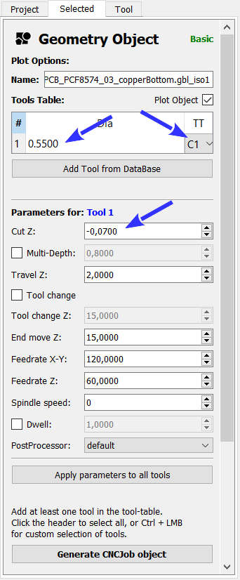
First, we “normalize” all tools and depth, open all geometry to transform in gcode, and set all tools to C1 so you can set depth to 0.07mm (or other depth if you prefer).
Join geometry
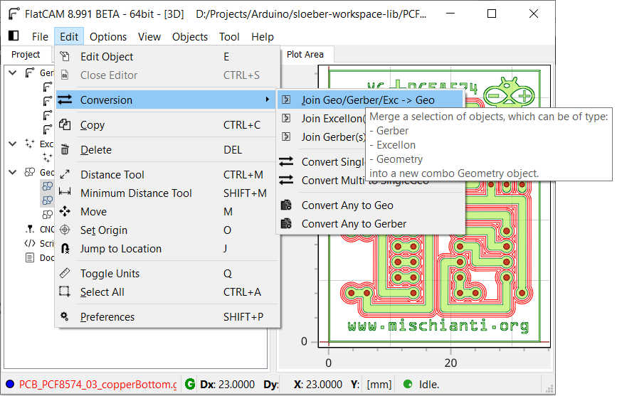
Another operation to get better readability of the project is to join the geometry with Edit --> Conversion --> Join Geo/Gerber/Exc -> Geo
Now I’m going to Join like so:
PCB_PCF8574_03_copperBottom.gbl_iso1 | 01-First2Passes |
PCB_PCF8574_03_copperBottom.gbl_iso2 | 02-LastPass |
PCB_PCF8574_03_copperBottom.gbl_iso3_ncc | 03-RemoveIslands |
PCB_PCF8574_03_logo.gbo_iso_paint | 04-Silkscreen |
PCB_PCF8574_03_contour.gm1_cutout | 05-Countour |
Generate GCode
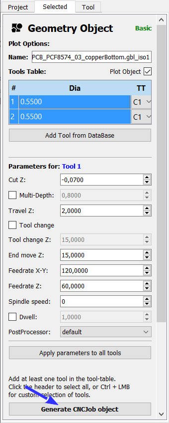
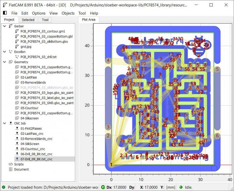
Now we will open all geometry files in sequence and click on Generate CNCJob object, but pay attention!!! You must select all Tools of Joined geometry to simplify. Click on the grid of tools and click “Crtl-A” first.
So now you have generated five gcode files:
01-First2Passes.nc02-LastPass_cnc.nc03-RemoveIslands_cnc.nc04-SilkScreen.nc05-Countour_cnc.nc
Drill gcode files
Now are missing only the gcode files to drill the PCB.
It would be best if you had bits like this.

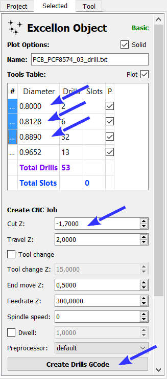
Click on the excellon file and choose a group of tips to use; I usually use 0.8 mm and 1 mm. I use the 1mm tip above 9.5mm, then set the depth (Cut Z) to -1.9mm I select the first three tools in the table (below 9.5mm) and generate the GCode file.
So you can create two gcode files: one 0.8mm bit one for the 1mm bit.
06-Drill_08_Bit.txt_cnc.nc07-Drill_09_Bit.txt_cnc.nc
Now we have covered all the milling parts, as you can see on the screen.
Mill the PCB
I started a tutorial on bCNC, and I used all these files as a demonstration; I began with probe and auto level and then all the milling files.
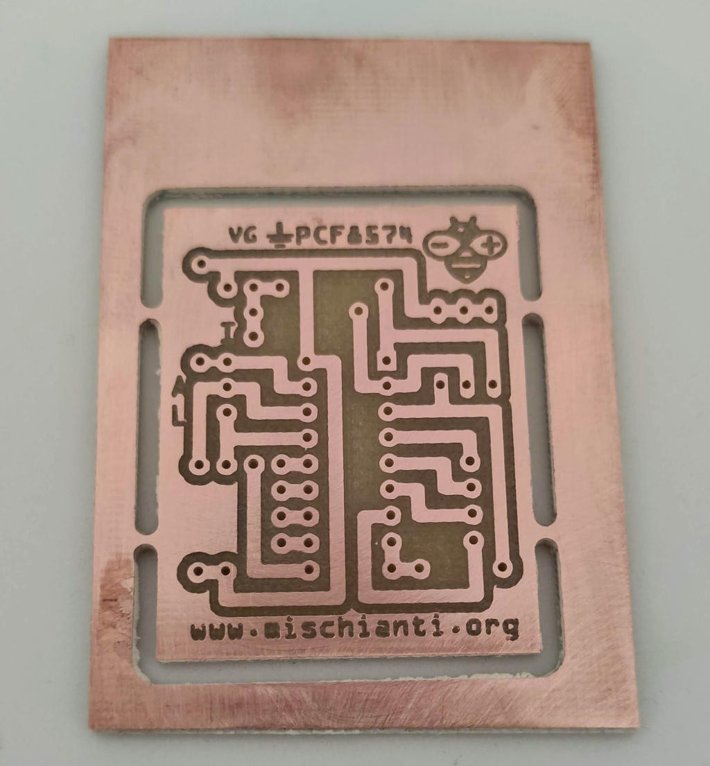
Final result
After cleaning It with sandpaper, the result is here. In this case, I use a 0.07mm depth, but when 0.07 is not sufficient, I raise the deep and redò the work.
Thanks
- FlatCAM practical tutorial: introduction, installation and import
- FlatCAM practical tutorial: copper traces geometry
- FlatCAM practical tutorial: clean non copper area
- FlatCAM practical tutorial: silkscreen geometry
- FlatCAM practical tutorial: contour
- FlatCAM practical tutorial: gcode and PCB milling
You can find Gerber, fritzing, images, and FlatCAM project files here.


Hi. Thanks to your Tutorial for me as newbee in CNC world.
I really want to know the miiling method to make a larger hole bigger than drilling bite.
Its a basic operation for CNC machine. But FlatCam did not support the milling. Need not to say the with polygon we could make the large hole but it is so complex to make a hole with polygon.
Would you let me know the way of milling the larger hole with smaller milling bite ?
Hi gmusojjang,
You can use a polygon, or you can add an image (of the hole) and mill that.
You can follow the same step of “Non linear contour” part of the tutorial.
FlatCAM practical tutorial: contour – Part 5
Bye Renzo