
FlatCAM practical tutorial: contour – Part 5
A feature that you can use every time is the final border cut to get your PCB.
In the previous version of FlatCAM, you could not follow a specified profile, but in this new version, this problem is avoided, and you can cut a non-linear border, like an Arduino shield.
Cut a normal border
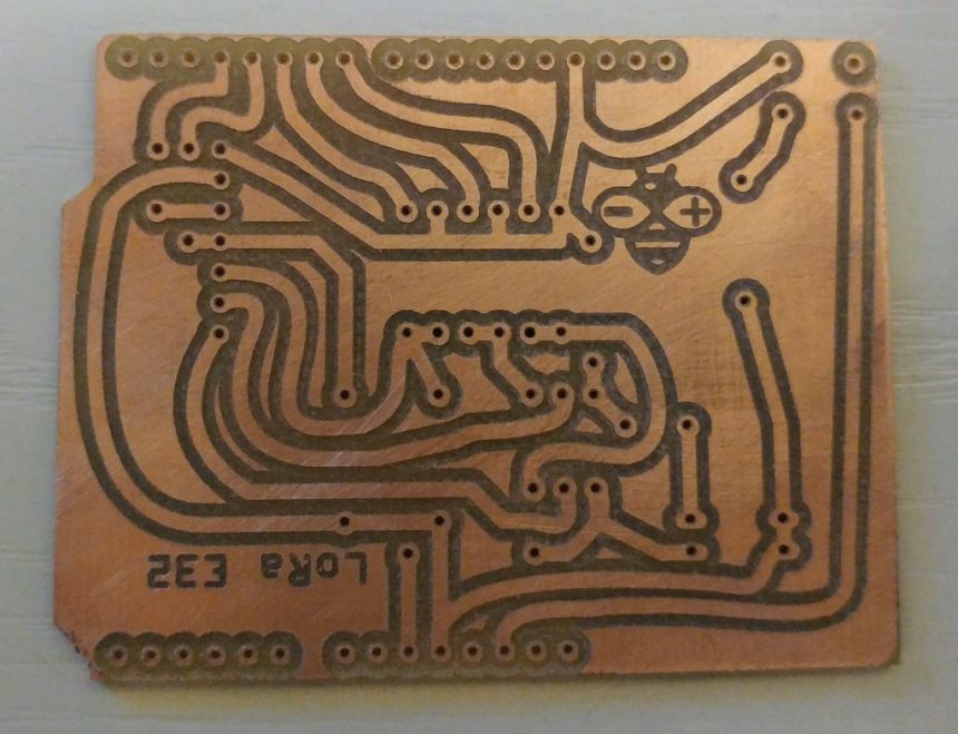
In this PCB, we have a regular border, and you only must go to select a PCB_PCF8574_03_contour.gm1 and click on Cutout Tool.
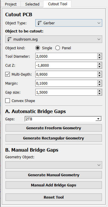
You arrive in a panel with a lot of parameters
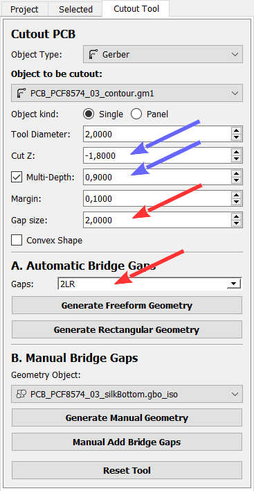
You can set the diameter of your tool. I use this bit to cut, and I get a clean cut.
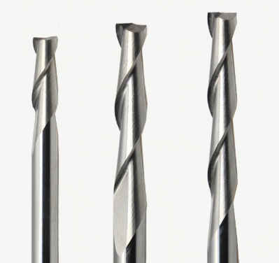
You can find here AliExpress
Now you must define how to cut this border (blue arrow):
- Cut Z: is the same parameter of other panel, here you specify how deep you want to go.
- Multi-Depth: this parameter is important here, and it is important whenever you need to remove a lot of material, here you specify how many material you want remove per pass, if you insert 2mm of Cut Z and 0,5mm of Multi-Depth FlatCAM generate 4 passes of 0,5mm.
A problem when you remove a frame is that at the end of the cut, the material can hit the bit and be damaged; you can prevent this problem with Gaps and Gap size.
You specify that you want to maintain a tiny part of the material to block the piece with that parameter.
- Gap size: it’s the amount of material you want to preserve;
- Gaps: specify where you want preserve the material.
- None: no preserve material;
- LR: left and right;
- TP: top and down;
- 4: 4 pieces of materia left, right, top and down;
- 2 LR: 2 pieces left and 2 pieces right;
- 2 TB: 2 pieces top and 2 pieces down;
- 8: 2 pieces on each side.
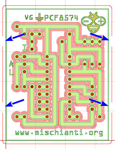
Now, if you set 2 LR and 1.5mm of Gap size and then click on Generate Rectangular Geometry (if you click Generate Freeform Geometry, the result is the same because the border is rectangular), you obtain this geometry.
Non linear border
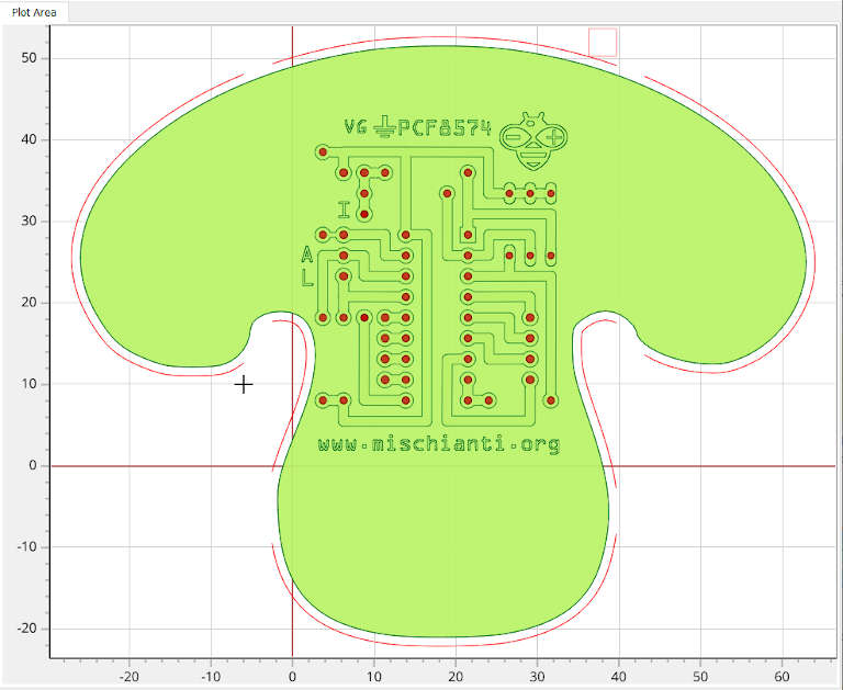
But.. if you need to create a mushroom PCB? The rectangular border is too reductive.
You can create your PCB with your IDE and, by IDE, create a particular border form, or you can import an image that will become your border.
So we are going to take this fantastic mushroom.
So we are going (as we have already seen in the second part of this tutorial) to import the image File --> Import --> SVG as Gerber Object.., then move It over PCB.
Then select the mushroom.svg and click on button Cutout Tool.
Check that on Object to be cutout combo mushroom.svg is selected and set you preferred parameter at the end click on Generate Freeform Geometry.
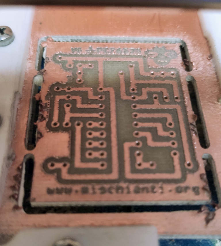
The result is this fantastic mushroom PCB.
Manual Add Bridge Gaps
Another feature that can be handy in this panel: Manual Add Bridge Gaps.
This tool created to break the border is very useful; if you select Object to be cut out a generic geometry, you can use Manual Add Bridge Gaps as rubber to delete some piece of Geometry.
You can define the size of our “rubber” by setting Gap size; then, you can click and delete all types of geometry, not only the contour.
Result of rectangular contour
Thanks
- FlatCAM practical tutorial: introduction, installation and import
- FlatCAM practical tutorial: copper traces geometry
- FlatCAM practical tutorial: clean non copper area
- FlatCAM practical tutorial: silkscreen geometry
- FlatCAM practical tutorial: contour
- FlatCAM practical tutorial: gcode and PCB milling
You can find Gerber, fritzing, images, and FlatCAM project files here.


