
Ebyte LoRa E32 device for Arduino, esp32 or esp8266: WOR (wake on radio) microcontroller and new Arduino shield – Part 6
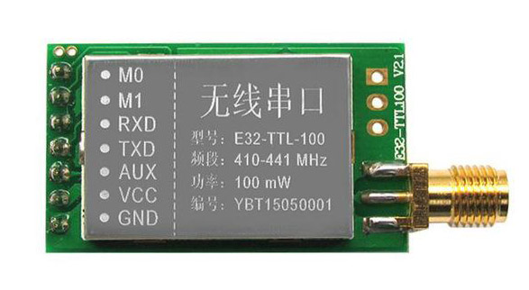
We have seen how this device (E32 UART LoRa based on popular SX1276/SX1278 Wireless Modules ) manages power saving, but If we use power saving only for the e32 the microcontroller continue to rest active, but we can use AUX pin to resolve this problem.
You can find module here AliExpress (433MHz 5Km) - AliExpress (433MHz 8Km) - AliExpress (433MHz 16Km) - AliExpress (868MHz 915MHz 5.5Km) - AliExpress (868MHz 915MHz 8Km)
If you have trouble like freeze device, you must put a pull-up 4.7k resistor or better connect to the device AUX pin.
First we must change some connection from the original connection schema, because in the original connection schema AUX pin isn’t connected to an interrupted pin, we are going to put AUX pin to pin 3 of Arduino, and shift all other pins.
So the new connection schema become like so:
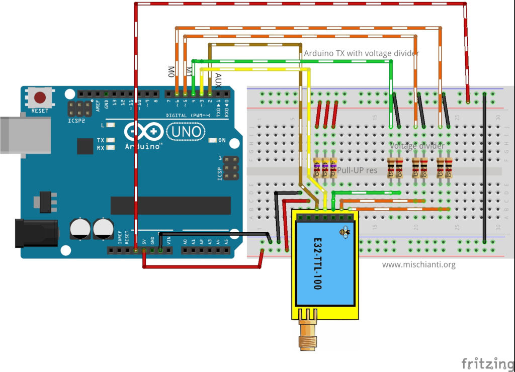
Now with AUX on interrupt pin we can use It to wake Arduino.
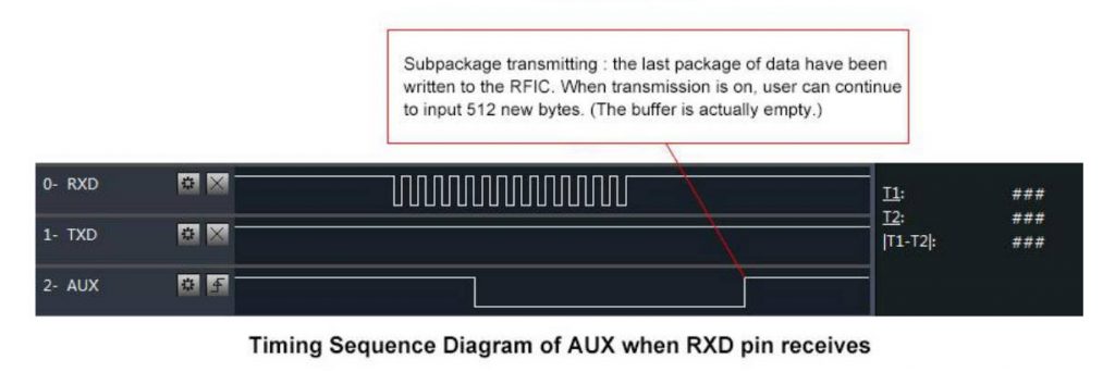
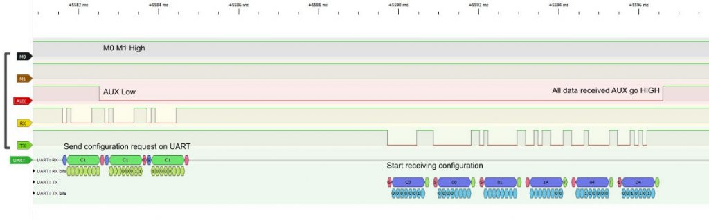
When you are in Sleep mode the e32 put on the buffer the data recived and go immediately LOW, when data is ready return HIGHT, LOW It’s perfect to wake the microcontroller.
Arduino wake up
As the e32 device Arduino have some sleep type, but for this test we are going to use power-down mode.
Library PowerDown
To manage power saving and sleep of Arduino device exist a beautiful library called LowPower.
You can download It directly here or you can go to the Git repository.
You must download the library and put It on Arduino library folder
How to put in sleep Arduino
The command to put on power down the microcontroller is quite simple
    // Enter power down state with ADC and BOD module disabled.
    // Wake up when wake up pin is low.
    LowPower.powerDown(SLEEP_FOREVER, ADC_OFF, BOD_OFF);
But we must specify that the device must wake when AUX pin go LOW
    // Allow wake up pin to trigger interrupt on low.
    attachInterrupt(1, AUX_PIN, LOW);

    // Enter power down state with ADC and BOD module disabled.
    // Wake up when wake up pin is low.
    LowPower.powerDown(SLEEP_FOREVER, ADC_OFF, BOD_OFF);

    // Disable external pin interrupt on wake up pin.
    detachInterrupt(1);
So the code to receive transmission become so:
/*
 * LoRa E32-TTL-100
 * Receive fixed transmission message on channel.
 * https://mischianti.org/lora-e32-device-for-arduino-esp32-or-esp8266-wor-wake-on-radio-the-microcontroller-also-and-new-arduino-shield-part-6/
 *
 * E32-TTL-100----- Arduino UNO or esp8266
 * M0         ----- 3.3v (To config) GND (To send) 7 (To dinamically manage)
 * M1         ----- 3.3v (To config) GND (To send) 6 (To dinamically manage)
 * TX         ----- RX PIN 3 (PullUP)
 * RX         ----- TX PIN 4 (PullUP & Voltage divider)
 * AUX        ----- PIN 2 (PullUP)
 * VCC        ----- 3.3v/5v
 * GND        ----- GND
 *
 */
#include "Arduino.h"
#include "LowPower.h"

#include "LoRa_E32.h"
// ---------- Arduino pins --------------
//LoRa_E32 e32ttl(4, 5, 3, 7, 6);
LoRa_E32 e32ttl(4, 5, 3); // Config without connect M0 M1
// Use pin 2 as wake up pin

const int wakeUpPin = 3;

//#include <SoftwareSerial.h>
//SoftwareSerial mySerial(4, 5); // Arduino RX <-- e32 TX, Arduino TX --> e32 RX
//LoRa_E32 e32ttl(&mySerial, 3, 7, 6);
// -------------------------------------
void printParameters(struct Configuration configuration);
void printModuleInformation(struct ModuleInformation moduleInformation);

void wakeUp()
{
	Serial.println("WAKE!");
}

//The setup function is called once at startup of the sketch
void setup()
{
	Serial.begin(9600);
	while (!Serial) {
	    ; // wait for serial port to connect. Needed for native USB
    }
	delay(100);

	e32ttl.begin();

//	e32ttl.resetModule();
	// After set configuration comment set M0 and M1 to low
	// and reboot if you directly set HIGH M0 and M1 to program
//	ResponseStructContainer c;
//	c = e32ttl.getConfiguration();
//	Configuration configuration = *(Configuration*) c.data;
//	configuration.ADDL = 3;
//	configuration.ADDH = 0;
//	configuration.CHAN = 0x04;
//	configuration.OPTION.fixedTransmission = FT_FIXED_TRANSMISSION;
//	configuration.OPTION.wirelessWakeupTime = WAKE_UP_250;
//
//    configuration.OPTION.fec = FEC_1_ON;
//    configuration.OPTION.ioDriveMode = IO_D_MODE_PUSH_PULLS_PULL_UPS;
//    configuration.OPTION.transmissionPower = POWER_20;
//
//    configuration.SPED.airDataRate = AIR_DATA_RATE_010_24;
//    configuration.SPED.uartBaudRate = UART_BPS_9600;
//    configuration.SPED.uartParity = MODE_00_8N1;
//
//	e32ttl.setConfiguration(configuration, WRITE_CFG_PWR_DWN_SAVE);
//	printParameters(configuration);
	// ---------------------------
	Serial.println();
	Serial.println("Start listening!");
    e32ttl.setMode(MODE_2_POWER_SAVING);

    // Allow wake up pin to trigger interrupt on low.
    attachInterrupt(1, wakeUp, LOW);

    // Enter power down state with ADC and BOD module disabled.
    // Wake up when wake up pin is low.
    LowPower.powerDown(SLEEP_FOREVER, ADC_OFF, BOD_OFF);

    // Disable external pin interrupt on wake up pin.
    detachInterrupt(1);
	Serial.println("OK listening!");


}

// The loop function is called in an endless loop
void loop()
{
	if (e32ttl.available()  > 1){
		ResponseContainer rs = e32ttl.receiveMessage();
        // First of all get the data
		String message = rs.data;
		Serial.print("Received --> ");
		Serial.print(rs.status.getResponseDescription());
		Serial.print(" - ");
		Serial.println(message);
	}
	delay(125);
}

void printParameters(struct Configuration configuration) {
	Serial.println("----------------------------------------");

	Serial.print(F("HEAD : "));  Serial.print(configuration.HEAD, BIN);Serial.print(" ");Serial.print(configuration.HEAD, DEC);Serial.print(" ");Serial.println(configuration.HEAD, HEX);
	Serial.println(F(" "));
	Serial.print(F("AddH : "));  Serial.println(configuration.ADDH, DEC);
	Serial.print(F("AddL : "));  Serial.println(configuration.ADDL, DEC);
	Serial.print(F("Chan : "));  Serial.print(configuration.CHAN, DEC); Serial.print(" -> "); Serial.println(configuration.getChannelDescription());
	Serial.println(F(" "));
	Serial.print(F("SpeedParityBit     : "));  Serial.print(configuration.SPED.uartParity, BIN);Serial.print(" -> "); Serial.println(configuration.SPED.getUARTParityDescription());
	Serial.print(F("SpeedUARTDatte  : "));  Serial.print(configuration.SPED.uartBaudRate, BIN);Serial.print(" -> "); Serial.println(configuration.SPED.getUARTBaudRate());
	Serial.print(F("SpeedAirDataRate   : "));  Serial.print(configuration.SPED.airDataRate, BIN);Serial.print(" -> "); Serial.println(configuration.SPED.getAirDataRate());

	Serial.print(F("OptionTrans        : "));  Serial.print(configuration.OPTION.fixedTransmission, BIN);Serial.print(" -> "); Serial.println(configuration.OPTION.getFixedTransmissionDescription());
	Serial.print(F("OptionPullup       : "));  Serial.print(configuration.OPTION.ioDriveMode, BIN);Serial.print(" -> "); Serial.println(configuration.OPTION.getIODroveModeDescription());
	Serial.print(F("OptionWakeup       : "));  Serial.print(configuration.OPTION.wirelessWakeupTime, BIN);Serial.print(" -> "); Serial.println(configuration.OPTION.getWirelessWakeUPTimeDescription());
	Serial.print(F("OptionFEC          : "));  Serial.print(configuration.OPTION.fec, BIN);Serial.print(" -> "); Serial.println(configuration.OPTION.getFECDescription());
	Serial.print(F("OptionPower        : "));  Serial.print(configuration.OPTION.transmissionPower, BIN);Serial.print(" -> "); Serial.println(configuration.OPTION.getTransmissionPowerDescription());

	Serial.println("----------------------------------------");

}
void printModuleInformation(struct ModuleInformation moduleInformation) {
	Serial.println("----------------------------------------");
	Serial.print(F("HEAD BIN: "));  Serial.print(moduleInformation.HEAD, BIN);Serial.print(" ");Serial.print(moduleInformation.HEAD, DEC);Serial.print(" ");Serial.println(moduleInformation.HEAD, HEX);

	Serial.print(F("Freq.: "));  Serial.println(moduleInformation.frequency, HEX);
	Serial.print(F("Version  : "));  Serial.println(moduleInformation.version, HEX);
	Serial.print(F("Features : "));  Serial.println(moduleInformation.features, HEX);
	Serial.println("----------------------------------------");

}
The result is that the Serial stop on line 91, when we receive the message the e32 wake itself and put AUX LOW, so Arduino wake with interrupt on AUX pin.
Here the sending sketch:
/*
 * LoRa E32-TTL-100
 * Send fixed broadcast transmission message to a specified channel.
 * https://mischianti.org/lora-e32-device-for-arduino-esp32-or-esp8266-wor-wake-on-radio-the-microcontroller-also-and-new-arduino-shield-part-6/
 *
 */
#include "Arduino.h"
#include "LoRa_E32.h"

// ---------- esp8266 pins --------------
LoRa_E32 e32ttl(D2, D3, D5, D7, D6); //, D5); //, D7, D6); // Config without connect AUX and M0 M1
// -------------------------------------

void printParameters(struct Configuration configuration);
void printModuleInformation(struct ModuleInformation moduleInformation);
//The setup function is called once at startup of the sketch
void setup()
{
	Serial.begin(9600);
	while (!Serial) {
	    ; // wait for serial port to connect. Needed for native USB
    }
	delay(100);

	while (!e32ttl.begin()) {
		    delay(2000); // wait for serial port to connect. Needed for native USB
	    }

	e32ttl.setMode(MODE_1_WAKE_UP);

//	e32ttl.resetModule();
	// After set configuration comment set M0 and M1 to low
	// and reboot if you directly set HIGH M0 and M1 to program
	ResponseStructContainer c;
	c = e32ttl.getConfiguration();
	Configuration configuration = *(Configuration*) c.data;
	printParameters(configuration);

//	configuration.SPED.uartBaudRate = UART_BPS_9600;
//	configuration.SPED.airDataRate = AIR_DATA_RATE_010_24;
	configuration.ADDL = 0x01;
	configuration.ADDH = 0x00;
	configuration.CHAN = 0x04;
	configuration.OPTION.fixedTransmission = FT_FIXED_TRANSMISSION;
	configuration.OPTION.wirelessWakeupTime = WAKE_UP_750;

	    configuration.OPTION.fec = FEC_1_ON;
	    configuration.OPTION.ioDriveMode = IO_D_MODE_PUSH_PULLS_PULL_UPS;
	    configuration.OPTION.transmissionPower = POWER_20;

	    configuration.SPED.airDataRate = AIR_DATA_RATE_010_24;
	    configuration.SPED.uartBaudRate = UART_BPS_9600;
	    configuration.SPED.uartParity = MODE_00_8N1;


	e32ttl.setConfiguration(configuration, WRITE_CFG_PWR_DWN_SAVE);
	printParameters(configuration);
	// ---------------------------


}
int i = 0;
// The loop function is called in an endless loop
void loop()
{
	i++;
	String mess = "Message to 00 03 04 deviceMessage to  ";
	String compMEss = mess+i;

	Serial.print(compMEss);
	Serial.print(" - ");
	ResponseStatus rs = e32ttl.sendFixedMessage(0, 3, 0x04, compMEss);
	Serial.println(rs.getResponseDescription());

	delay(8000);

}

void printParameters(struct Configuration configuration) {
	Serial.println("----------------------------------------");

	Serial.print(F("HEAD : "));  Serial.print(configuration.HEAD, BIN);Serial.print(" ");Serial.print(configuration.HEAD, DEC);Serial.print(" ");Serial.println(configuration.HEAD, HEX);
	Serial.println(F(" "));
	Serial.print(F("AddH : "));  Serial.println(configuration.ADDH, DEC);
	Serial.print(F("AddL : "));  Serial.println(configuration.ADDL, DEC);
	Serial.print(F("Chan : "));  Serial.print(configuration.CHAN, DEC); Serial.print(" -> "); Serial.println(configuration.getChannelDescription());
	Serial.println(F(" "));
	Serial.print(F("SpeedParityBit     : "));  Serial.print(configuration.SPED.uartParity, BIN);Serial.print(" -> "); Serial.println(configuration.SPED.getUARTParityDescription());
	Serial.print(F("SpeedUARTDatte  : "));  Serial.print(configuration.SPED.uartBaudRate, BIN);Serial.print(" -> "); Serial.println(configuration.SPED.getUARTBaudRate());
	Serial.print(F("SpeedAirDataRate   : "));  Serial.print(configuration.SPED.airDataRate, BIN);Serial.print(" -> "); Serial.println(configuration.SPED.getAirDataRate());

	Serial.print(F("OptionTrans        : "));  Serial.print(configuration.OPTION.fixedTransmission, BIN);Serial.print(" -> "); Serial.println(configuration.OPTION.getFixedTransmissionDescription());
	Serial.print(F("OptionPullup       : "));  Serial.print(configuration.OPTION.ioDriveMode, BIN);Serial.print(" -> "); Serial.println(configuration.OPTION.getIODroveModeDescription());
	Serial.print(F("OptionWakeup       : "));  Serial.print(configuration.OPTION.wirelessWakeupTime, BIN);Serial.print(" -> "); Serial.println(configuration.OPTION.getWirelessWakeUPTimeDescription());
	Serial.print(F("OptionFEC          : "));  Serial.print(configuration.OPTION.fec, BIN);Serial.print(" -> "); Serial.println(configuration.OPTION.getFECDescription());
	Serial.print(F("OptionPower        : "));  Serial.print(configuration.OPTION.transmissionPower, BIN);Serial.print(" -> "); Serial.println(configuration.OPTION.getTransmissionPowerDescription());

	Serial.println("----------------------------------------");

}
void printModuleInformation(struct ModuleInformation moduleInformation) {
	Serial.println("----------------------------------------");
	Serial.print(F("HEAD BIN: "));  Serial.print(moduleInformation.HEAD, BIN);Serial.print(" ");Serial.print(moduleInformation.HEAD, DEC);Serial.print(" ");Serial.println(moduleInformation.HEAD, HEX);

	Serial.print(F("Freq.: "));  Serial.println(moduleInformation.frequency, HEX);
	Serial.print(F("Version  : "));  Serial.println(moduleInformation.version, HEX);
	Serial.print(F("Features : "));  Serial.println(moduleInformation.features, HEX);
	Serial.println("----------------------------------------");

}
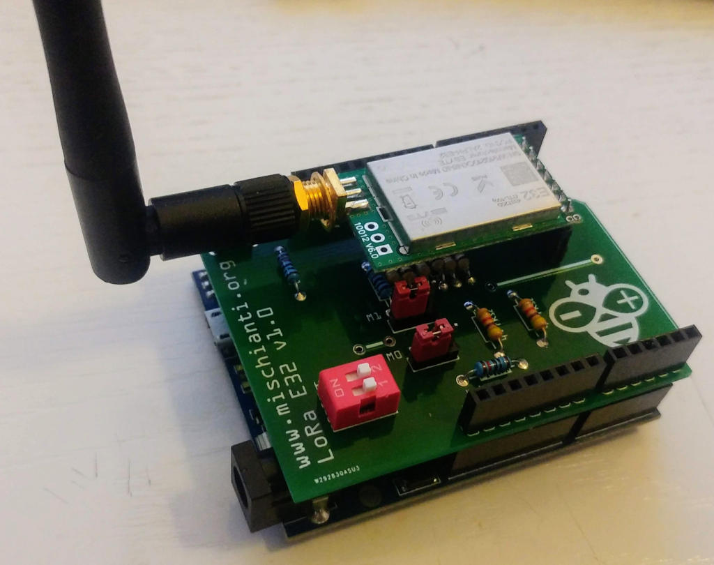
Arduino UNO shield
I create also an Arduino shield very usefully to use.
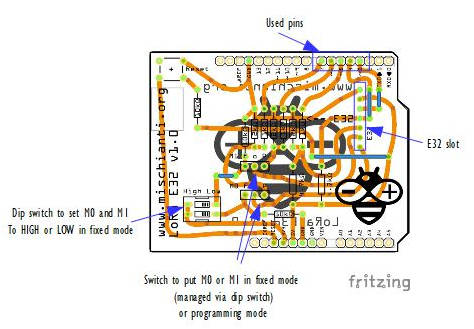
With this board you can use this device directly without problem or voltage divider.
The configuration is this:
LoRa_E32 e32ttl(4, 5, 3, 7, 6);
Than you can use all examples inside the library, you can use pin 6 and 7 to do a full connection or disable they and put M0 and M1 as you want with dipswitch.
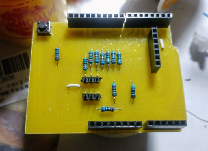
Here the first test, seems all ok.
Now we are going to do a massive production.
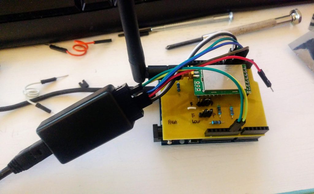
Ready to go
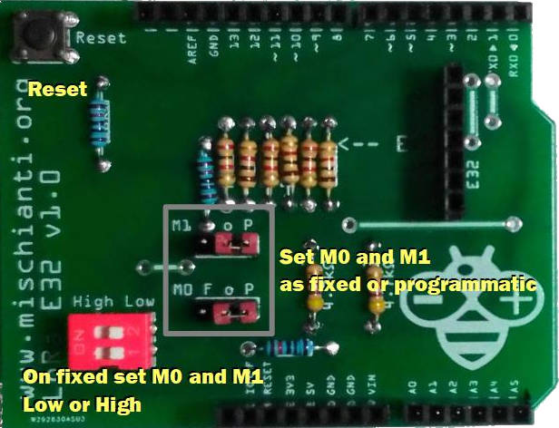
The shield have some jumper and dip switch to configure M0 and M1.
If you want set M0 and M1 to a fixed value you must put jumper to F, if you want control via pin to P.
If you set to F you must put dip switch on property value Low or High.
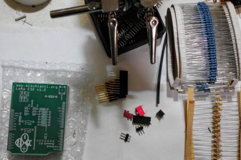
Shopping List
You can find here AliExpress (433MHz 5Km) - AliExpress (433MHz 8Km) - AliExpress (433MHz 16Km) - AliExpress (868MHz 915MHz 5.5Km) - AliExpress (868MHz 915MHz 8Km)
Amount Part Type Properties 1 Lora E32-TTL-100 variant 1; voltage 3-5V; type Basic 1 DIP SWITCH channels 1; package dipswitch-02 2 Generic male header – 3 pins pins 3; pin spacing 0.1in (2.54mm); hole size 1.0mm,0.508mm; form ♂ (male); package THT; row single 1 Arduino Uno (Rev3) type Arduino UNO (Rev3) 3 4.7kΩ Resistor bands 4; tolerance ±5%; pin spacing 400 mil; package THT; resistance 4.7kΩ 3 1kΩ Resistor bands 4; tolerance ±5%; pin spacing 400 mil; package THT; resistance 1kΩ 3 2kΩ Resistor bands 4; tolerance ±5%; pin spacing 400 mil; package THT; resistance 2kΩ 3 10kΩ Resistor bands 4; tolerance ±5%; pin spacing 400 mil; package THT; resistance 10kΩ 1 Momentary Tactile Push Button package [THT] 1 Generic female header – 7 pins Pin spacing 0.1in (2.54mm); 2 Generic male/female header – 8 pins Pin spacing 0.1in (2.54mm); 1 Generic male/female header – 6 pins Pin spacing 0.1in (2.54mm); 1 Generic male/female header – 10 pins Pin spacing 0.1in (2.54mm);
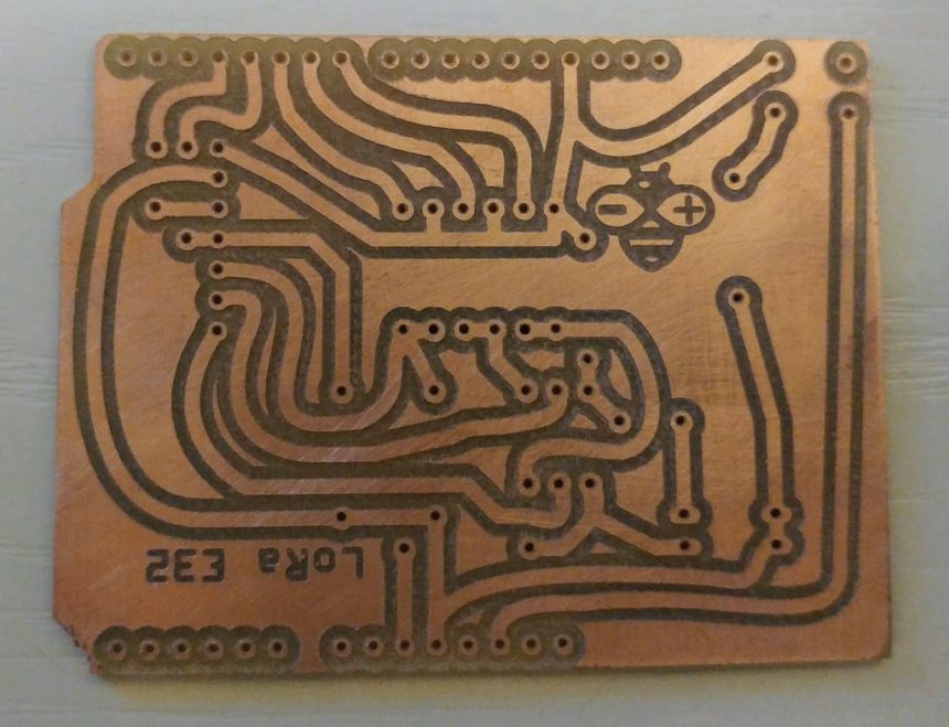
You can get the PCB from PCBWay 10 at 5$ PCBWay

Here my Crtistmas present
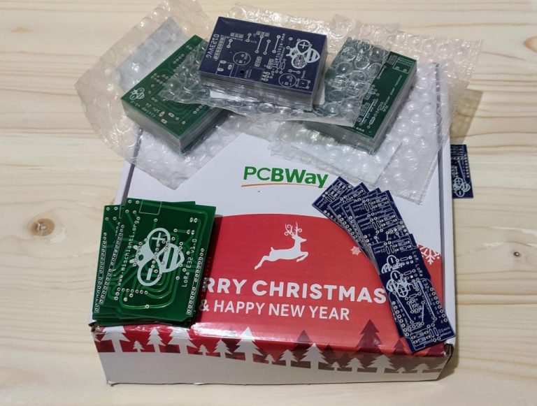
I chose this manufacturer because at the same cost it offers excellent quality, in the first screen it is possible to make countless options suitable for every need.
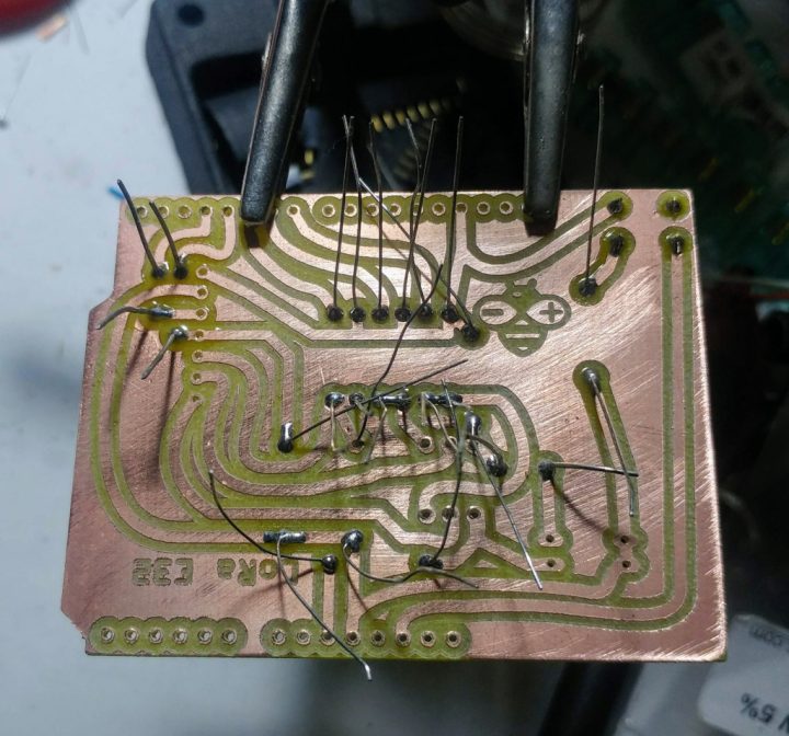
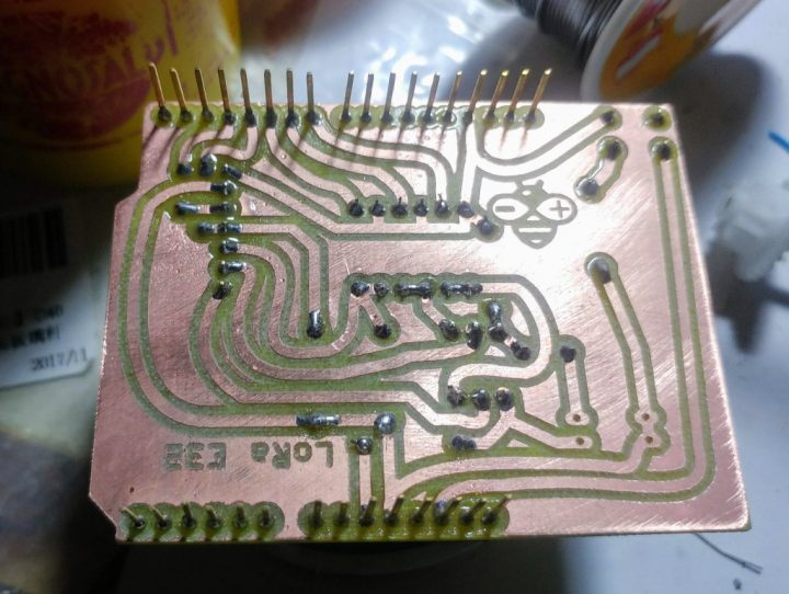
The board as you can see on various photo is very beautiful and simply to solder.
Assembly video
Here the soldering video.
Here the result
Thanks
- LoRa E32 device for Arduino, esp32 or esp8266: settings and basic usage
- LoRa E32 device for Arduino, esp32 or esp8266: library
- LoRa E32 device for Arduino, esp32 or esp8266: configuration
- LoRa E32 device for Arduino, esp32 or esp8266: fixed transmission
- LoRa E32 device for Arduino, esp32 or esp8266: power saving and sending structured data
- LoRa E32 device for Arduino, esp32 or esp8266: WOR (wake on radio) microcontroller and Arduino shield
- LoRa E32 device for Arduino, esp32 or esp8266: WOR (wake on radio) microcontroller and WeMos D1 shield
- EByte LoRa E32 device for Arduino, esp32 or esp8266: WOR (wake on radio) and new ESP32 shield
- Ebyte LoRa E32 with STM32: WOR (wake on radio) and new STM32 shield
- Mischianti Arduino LoRa shield (Open source)
- Mischianti WeMos LoRa shield (Open source)
- Mischianti ESP32 DOIT DEV KIT v1 shield (Open source)
- STM32F1 Blue-Pill EByte LoRa E32, E22, and E220 Shield
- STM32F4 Black-Pill EByte LoRa E32, E22, and E220 Shield


Can we use all the e32 modules so also the 915 and 868 with your library?
Hi,
I hope yes, I add some define to manage other frequency and other power, but now I test only power (100mw e 1w with correct db). There are more information on part 3 when I explain all configuration parameter.
#define FREQUENCY_433
#define FREQUENCY_170
#define FREQUENCY_470
#define FREQUENCY_868
#define FREQUENCY_915
But are untested, I have an 868 module, but I need time to check It.
If you try and find some problems ask me and we can try to resolve.
Bye Renzo
dear I buy the PCB board I check the connection it use D3 to d7 not as per code would you justefiy
Hi,
You must refer to the relative article of the shield
Wemos shield article here I explain why I change the pin in
LoRa_E32 e32ttl(D3, D4, D5, D7, D6);
Tell me if there are other problems.
Bye Renzo
In all your examples, you assume that we work with an Arduino UNO, therefore you use Setserial, I work with an Arduino Mega, therefore I want to use Rx and Tx for hardware.
How do you change this code?
#include
SoftwareSerial mySerial(2, 3); // RX, TX
LoRa_E32 e32ttl(&mySerial, 5, 7, 6);
For instance to work with Serial3 at the Arduino Mega?
Thanks in advance.
Hi Alejandro,
It’s fully documented on LoRa E32 device for Arduino, esp32 or esp8266: library – Part 2 you can pass the HardwareSerial in the contructor.
LoRa_E32 e32ttl(&Serial3, 5, 7, 6);If you intend the shield, this work only with uno, because the pins that can be used as RX from microcontroller is different, Check this I start design a configurable versione of the shield, but I think first release the e22 version of the library.
Bye Renzo
Renzo, when I try to compile:
LoRa_E32 e32ttl(Serial3, 5, 7, 6);
It give me:
prueba_03:7:36: error: no matching function for call to ‘LoRa_E32::LoRa_E32(HardwareSerial&, int, int, int)’
LoRa_E32 e32ttl100(Serial3, 3, 7, 6);
^
In file included from /home/afernandez/icsa/prueba_03/prueba_03.ino:4:0:
/home/afernandez/Arduino/libraries/ LoRa_E32/LoRa_E32.h:194:4: note: candidate: LoRa_E32::LoRa_E32(HardwareSerial*, byte, byte, byte, byte, byte, UART_BPS_RATE, uint32_t)
LoRa_E32(HardwareSerial* serial, byte rxPin, byte txPin, byte auxPin, byte m0Pin, byte m1Pin, UART_BPS_RATE bpsRate = UART_BPS_RATE_9600, uint32_t serialConfig = SERIAL_8N1);
^~~~~~~~
I changed the number of arguments, the compiler always was complaining
Pass the reference
LoRa_E32 e32ttl(&Serial3, 5, 7, 6);Bye Renzo
Bravo, bravísimo!!!
LoRa_E32 e32ttl100(&Serial3, 3, 7, 6,UART_BPS_RATE_9600,SERIAL_8N1);
That work;
Regards.
I’m happy you’ve found the solution.
Bye Renzo
Hi, I buy the PCB board v1.4 for vemos. I also buy a 2k resistors but on the pcb you have writing 10k !
Ops.. sorry, It’s 2k, I’m going to update the PCB.
Thanks Bye
Perfect !
another remark : you don’t put jumper caps (x2) in your shopping list
Hehehehe.. yes It’s true I’m going to add..
Bye Renzo
here is a great job!
I thought I saw an encrypt function?
Thanks Ludo,
It’s true, but I stop that develop, the size of packet is 58 byte, so an encription function isn’t a good solution, I finish to develop E22 library that support 240 bytes package, proprably I’m going to do something there.
I haven’t so much time so I put strenght on a Web Manager first for E32 next for E22, here a preview
hi !
the addressing of the modules is indeed 0x0000.
So there are 65535 addresses per channel?
Hi ludophot,
yes, about 65000, there are 2 bytes ADDL ADDH for addressing, so 255*255 possibility.
Bye Renzo
Hello Mischianti thanks for your share, I have a question, Is it possible for E32433T30D model to work in duplex mode ? How can I switch from transmitting mode to receiving mode or vice versa ? If you have an simplest example about it, can you share with me ?
Thanks in advance ?
Hi Kadir,
you can switch from wake up, sleep and normal mode with the command
setMode,if you want to go in sleep mode you call
when you are waked you call
if you want wake a sleep device you set
If you need more detailed info open a topic on forum.
Bye Renzo
Renzo,
do you have some advise on why my dual purpose server (receiver) takes a lot of message sends to wake up my node. I’ve attached part of my code , I’m using modbus register 40014 with a value of 1 to trigger the wake up of the nodes (once the nodes are woken they then send back a value that i place in a modbus register on the server). The amount of messages sent varies from sometimes maybe 5 to sometimes as much as 20 to 30 sends to wake up the node. I’ve tried numerous send messages including broadcast all with similar results.
below is my sending arrangement.
	if (regBank.get(40014) == 1) {
		e32ttl.begin();
		e32ttl.setMode(MODE_1_WAKE_UP);
		delay(500); // half a second delay
		Serial.println("wake up world!"); // display wake function to test modbus write to register worked

//	below does work but random on number of attempts it takes sometimes 10 or more sends before it wakes up
		i++;
		struct Message {
			char type[6] = "LOT19";
			char message[8] = "Flow_LH";
			word flow;
		} message;

		message.flow = 65519;

		ResponseStatus rs = e32ttl.sendFixedMessage(0, 3, 4, &message,
				sizeof(Message));
		Serial.println(rs.getResponseDescription());

//	below does work for waking my wemos server, takes 2 messages
		i++;
		String mess = "Message to 00 01 04 deviceMessage to ";
		String compMEss = mess + i;

		Serial.print(compMEss);
		Serial.print(" – ");
		ResponseStatus rs = e32ttl.sendFixedMessage(0, 1, 0x04, compMEss);
		Serial.println(rs.getResponseDescription());
		above does
		work
		for waking my wemos server, takes 2 messages

//	below 2 lines did work but random amounts of sends before it wakes
		ResponseStatus sendBroadcastFixedMessage(byte CHAN, const String message);
		ResponseStatus rs = e32ttl.sendBroadcastFixedMessage(0x04,
				"Message to a devices of a channel");

//	below 3 lines did wake my server but took a lot of sends before it woke
		Serial.println("Send message to 00 03 04");
		ResponseStatus rs = e32ttl.sendFixedMessage(0, 3, 0x04,
				"Message to 00 01 04 deviceMessage to 1 ");
		Serial.println(rs.getResponseDescription());

//	below 2 lines did wake my server but took a lot of sends before it woke
		ResponseStatus rs = e32ttl.sendBroadcastFixedMessage(4,
				"Send message to channel 4 and all of my nodes that exist");
		Serial.println(rs.getResponseDescription());
this is my timing wake line : configuration.OPTION.wirelessWakeupTime = WAKE_UP_250;//WAKE_UP_250;, also tried 750, also tried 2000
on the node I have it set at 250
What have I missed ?
Hi Craig,
everything seems ok, can you one a Topic and put the client and server configuration with the relative wiring and code.
Thanks Renzo
hi renzo ;
can you send me gerber file your device lore e32 v1.0
Hi Sezgin,
sorry i have an agreement with PCBWay.
You can find It here.
Bye Renzo
hi renzo ;
link not working.
hi renzo;
link not working
Sorry I fixed It.
Bye Renzo
hi Renzo;
I installed the system as you described.
When I put the arduino nano in sleep mode, the current drawn fluctuates between 150 microamperes and 1.8 milliamperes. When I remove the lora module from the system, only the arduino draws a stable current of 150 microamperes. Why does the lora module make this current fluctuation, is it normal? where am i doing wrong.
Hi Sezgin,
the LoRa module check the incoming message every milliseconds set on configuration
configuration.OPTION.wirelessWakeupTime = WAKE_UP_250;if you want reduce the power consumption you must raise the
wirelessWakeupTime, but the sender must have a bigger value also.For the sender
wirelessWakeupTimeis the preamble to wake the receiver.Bye Renzo
hi Renzo;
I set the wake up setting of the sender and the receiver to 2000 ms. The result is good. 200 microamperes. So, is there a performance disadvantage to using the system like this?
No no, 2000ms is the best power-saving performance.
Every 2secs when the receiver check messages the device generate the fluctuation.
Bye Renzo
Hi Renzo ;
So how do you suggest I set the wake up time of the receiver and transmitter?
Hi Sezgin,
the better power usage is with 2000 to sender and receiver, so you con try this situation.
But you must test if in production It’s work correctly, if the receiver don’t wake correctly you must reduce the receiver time to check more time the message in the Air.
Bye Renzo
Hi Renzo;
Would using arduino pro mini 3v3 8 mhz be more advantageous in terms of ttl level and power saving?
Hi sezgin,
yes I think it’s bette a 3v3 logic level microcontroller, but remember to use 5v power supply to the E32 if you need a very long range connection.
Bye Renzo
Hi,
If we want to use an external battery to feed the E32 module, what changes we should do with respect to the shield.
BTW, I purchased the shields from PCBWAY and thei pcbs are top notch.
Thank you
Hi jhon,
to have the better performance from e32 it must powered with 5v, so i think you must use a solution like
Emergency power bank homemade
With a tp to recharge 18650 battery and power the arduino with 5v via step-up.
Bye Renzo