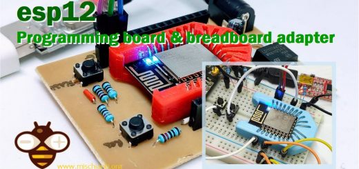
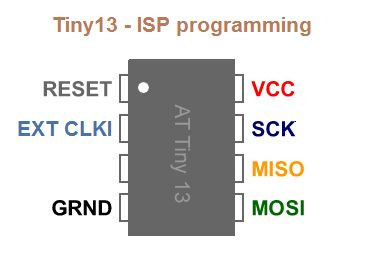
ATtiny Programmer Board (ArduinoUNO As ISP)
ATtiny13/ATtiny13a/ATtiny25/ATtiny45/ATtiny85
I really like the ATtiny and programming it, so I built a simple board to use Arduino UNO as ISP in a faster way.
With the original Arduino UNO, there is a little variant because compatible one have another 5v VCC over RESET pin, Arduino UNO has IOREF instead, but don’t worry look at the schema to make the simple change.
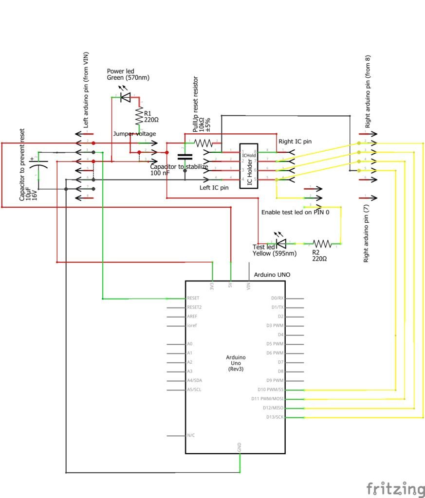
Schema
In github project you can find the fritzing file with simple examples and schema.
Material
I use a perfored board.
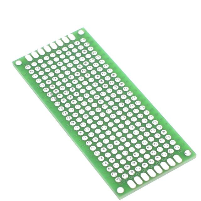
You need prototype board 3x7 Aliexpress
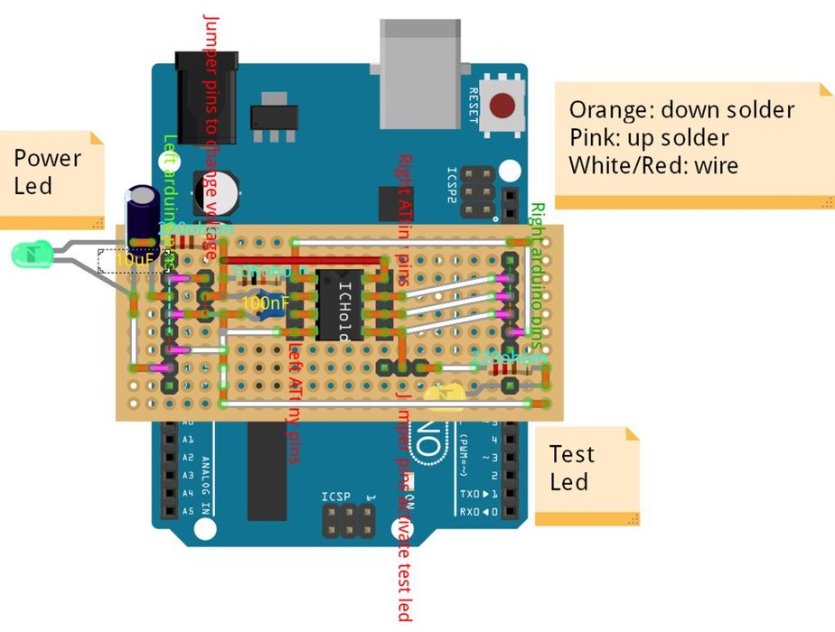
To switch Voltage (to use 3.3v or 5v) and to enable test LED, I use a smd on/off button instead of a pin with a jumper.
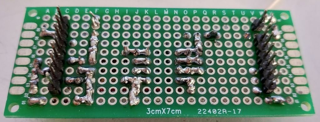
The board is double sided so I can attach pin and components up and down the board.
AmountPart TypeProperties
- 1 Arduino Uno (Rev3)
Here the Arduino Arduino UNO - Arduino MEGA 2560 R3 - Arduino Nano - Arduino Pro Mini
- 1 Electrolytic Capacitor capacitance 10µF
- 1 Ceramic Capacitorcapacitance 100 nF
- 1 IC Holderpin spacing 300mil; pins 8
- 1 Green LED package 3 mm [THT]; colore Green (570nm); leg yes
- 1 Yellow LED package 3 mm [THT]; colore Yellow (595nm); leg yes
- 1 10kΩ Resistor
- 2 220Ω Resistor
- Generic male header form ♂ (male); hole size 1.0mm,0.508mm; pin spacing 0.1in (2.54mm);
- Generic female header form ♀ (female); hole size 1.0mm,0.508mm; pin spacing 0.1in (2.54mm);
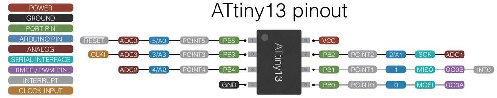
ATtiny13a Variant
I buy ATtiny13a very low cost IC (less than 0.5€), with 4 analog pin and 2 PWM/TIMER PIN.
ATtiny 13a Aliexpress Attiny 13a discrete - Aliexpress Attiny 13a SMD
Board V01
First version of board with no led indicators.
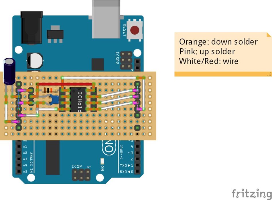
This version work only with fake Arduino.
Fritzing here.
Board V01 (Original ArduinoUNO)
As you can see for Original Arduino uno you must add a wire to give 5v voltage to switch.
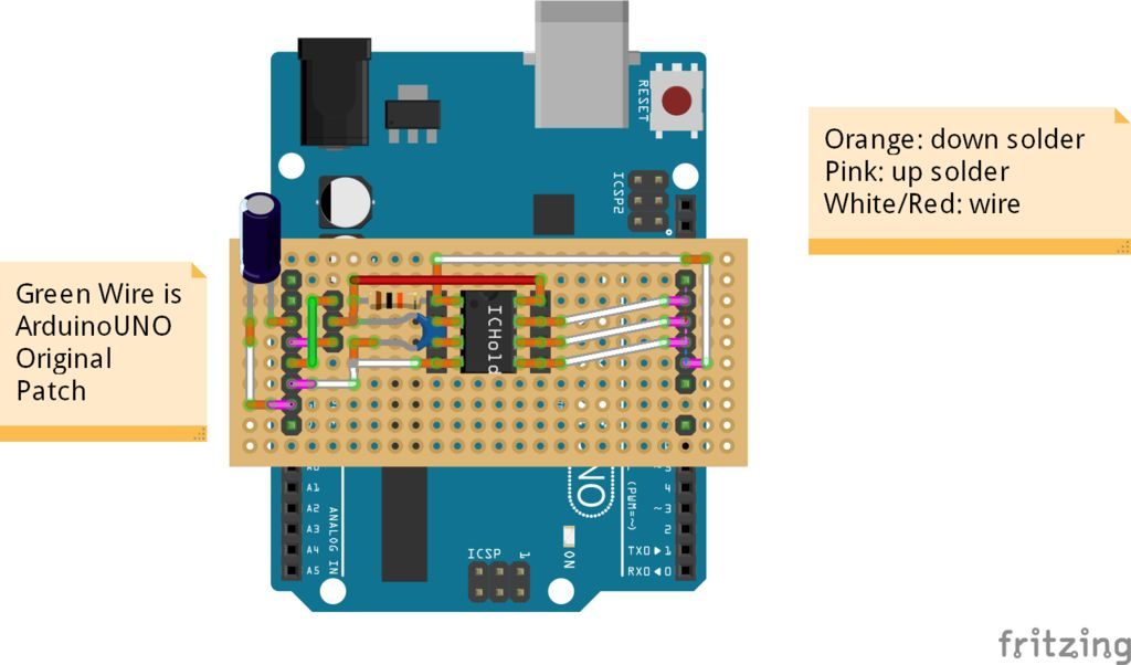
Fritzing here.
Board V02 (power Led)
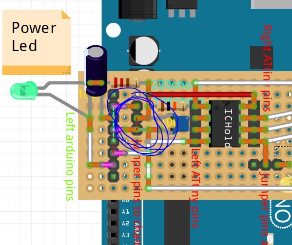
Add green led to control if board have power supply.
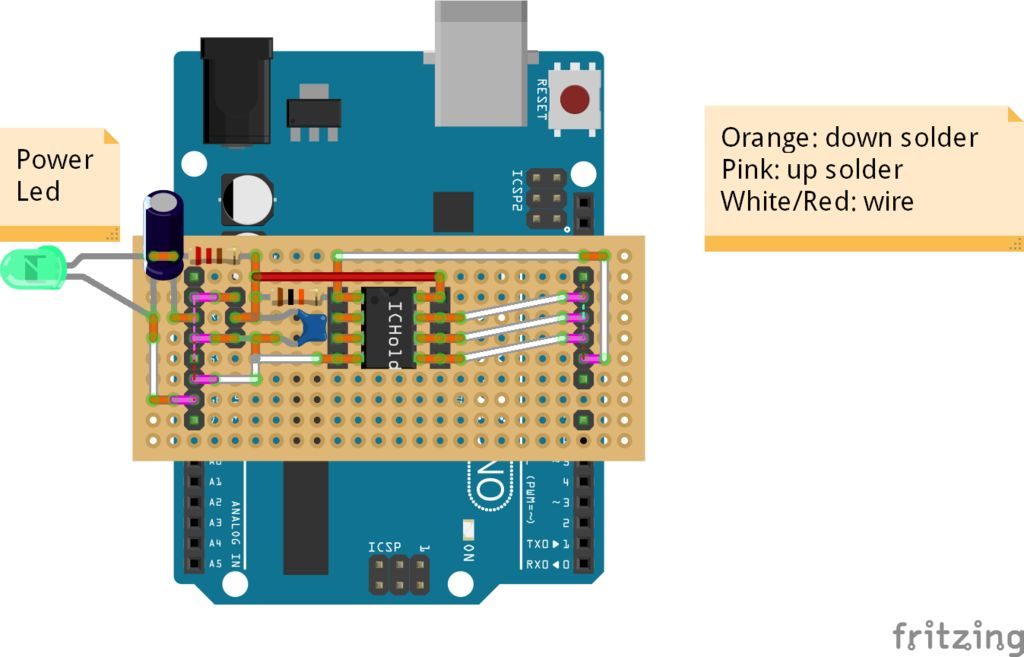
Fritzing here.
Board V03 (test Led)
I add a very usefully test led, to check if all is connected correctly.
Fritzing here.
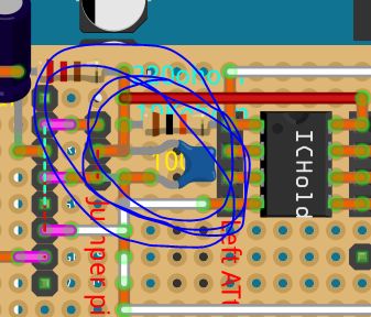
Board: Voltage Jumper
ATtiny can work at various voltage so I insert a jumper to select ATtiny operating voltage 3v or 5v power supply.
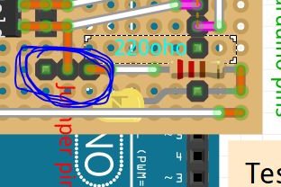
Board: Test Led Jumper
To test if It’s all ok on board I add a test led that can be activated by that jumper.
Board: Reset Capacitor
To prevent reset when upload code It’s important to add a capacitor to reset pin of Arduino.
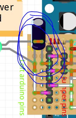
Board: Voltage Capacitor and Reset Resistor
Other important thing is the capacitor to stabilize the voltage and pullup resistor to reset pin of ATtiny.
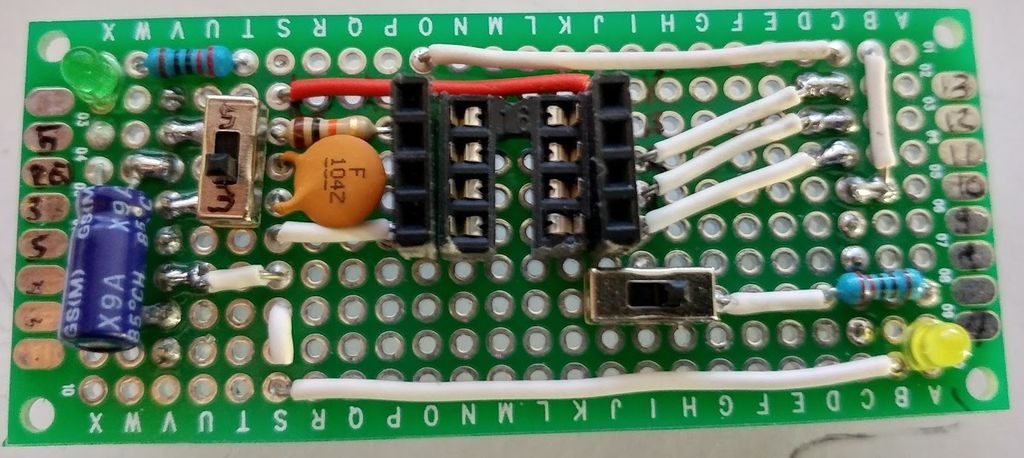
Assembled Board
The realization is quite simple and the result is very usefully.
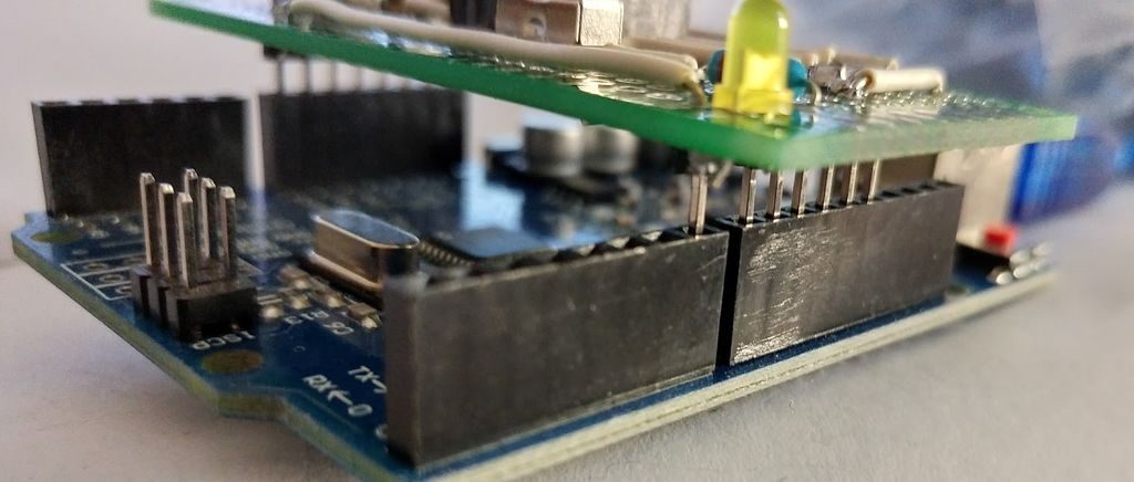
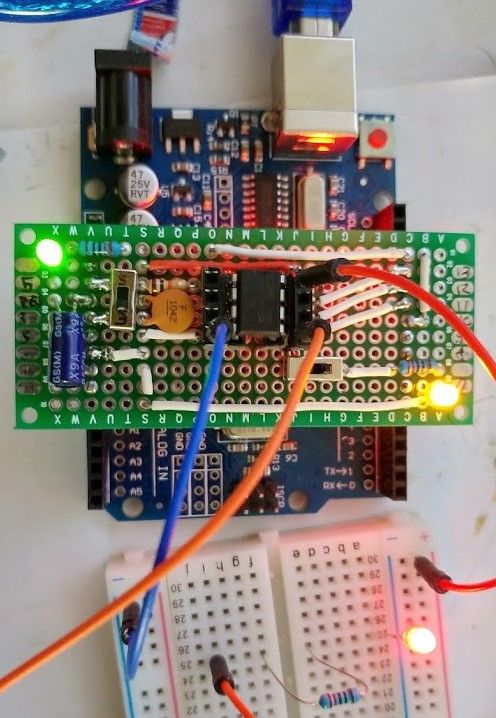
How Board Fit on Arduino
Mount board on Arduino.
How to Program an ATtiny: Prepare ArduinoUNO to Use It As ISP
- In Arduino IDE select ArduinoUNO board (Tool –> Board –> ArduinoUNO – Strumenti –> Scheda –> ArduinoUNO);
- Than open ArduinoISP example file (File –> Examples/Esempi –> 11.ArduinoISP –> ArduinoISP);
- Upload Arduino (Sketch –> Upload/Carica);
- Close IDE.
Add Support for ATtiny: ATtiny13/ATtiny13a
- Open the Arduino IDE;
- Open the File > Preferences menu item;
- Enter the following URL in Additional Boards Manager URLs:https://mcudude.github.io/MicroCore/package_MCUdu… ;
- Open the Tools > Board > Boards Manager… menu item;
- Wait for the platform indexes to finish downloading;
- Scroll down until you see the MicroCore entry and click on it;
- Click Install;
- After installation is complete close the Boards Manager window.
Add Support for ATtiny: ATtiny25/ATtiny45/ATtiny85
- Open the Arduino IDE;
- Open the File > Preferences menu item;
- Enter the following URL in Additional Boards Manager URLs:https://raw.githubusercontent.com/damellis/attiny… ;
- Open the Tools > Board > Boards Manager… menu item;
- Wait for the platform indexes to finish downloading;
- Scroll down until you see the MicroCore entry and click on it;
- Click Install;
- After installation is complete close the Boards Manager window.
How to Program an ATtiny: Upload to ATtiny
- Attach board to ArduinoUNO;
- Insert ATtinyXX;
- If the board is v03 than activate test led otherwise using a breadboard and take VCC from upper right pin of attiny and GND to down left pin, than connect 0 pin (down right) to a led (on next video);
- Select board with correct setting and PORT (Tools –> Board/Strumenti –> Scheda);
- Select Arduino as ISP (Tools –> Programmer –> Arduino as ISP/Strumenti –> Programmatore –> Arduino as ISP);note: Arduino as ISP is different from ArduinoISP.
- Upload program (Sketch –> Upload from programmer / Schetch –> Carica tramite un programmatore).
Sample Sketch
If the board is v03 than activate test led otherwise using a breadboard and take VCC from upper right pin of attiny and GND to down left pin, than connect 0 pin (down right) to a led (on video).
A simple scketch to upload to ATtiny
#define PIN 0
void setup()
{
  pinMode(PIN, OUTPUT);
}

void loop()
{
  digitalWrite(PIN, LOW);
  delay(500);
  digitalWrite(PIN, HIGH);
  delay(500);
}
Thanks
In github project you can find some additional info and schema.