
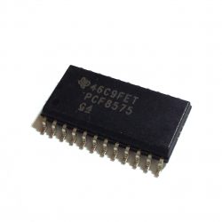
PCF8575 i2c 16 bit digital I/O expander
This 16-bit I/O expander for the two-line bidirectional bus (I2C) is designed for 2.5-V to 5.5-V VCC operation.
The PCF8575 device provides general-purpose remote I/O expansion for most microcontroller families by way of the I2C interface [serial clock (SCL), serial data (SDA)].
The device features a 16-bit quasi-bidirectional input/output (I/O) port (P07–P00, P17–P10), including latched outputs with high-current drive capability for directly driving LEDs. Each quasi-bidirectional I/O can be used as an input or output without the use of a data-direction control signal. At power on, the I/Os are high. In this mode, only a current source to VCC is active.
- I2C to Parallel-Port Expander
- Open-Drain Interrupt Output
- Low Standby-Current Consumption of 10 µA Max
- Compatible With Most Microcontrollers
- 400-kHz Fast I2C Bus
- Address by Three Hardware Address Pins for Use of up to Eight Devices
- Latched Outputs With High-Current Drive Capability for Directly Driving LEDs
- Current Source to VCC for Actively Driving a High at the Output
- Latch-Up Performance Exceeds 100 mA Per JESD 78, Class II
- ESD Protection Exceeds JESD 22
- 2000-V Human-Body Model
- 200-V Machine Model
- 1000-V Charged-Device Model
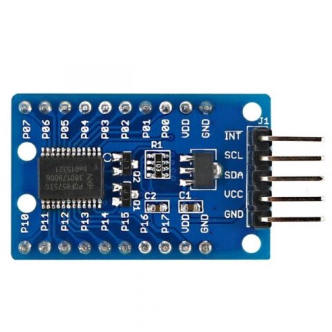
Module Connections
The connections to the module are straight forward.
- Supply 3.3 or 5V power and ground.
- Connect I2C SCL and SDA lines to same on the MCU.
- If used, connect the INT line to an interrupt input on the MCU and use a pull-up resistor.
I write a library to use i2c pcf8575 IC with arduino and esp8266.
So can read and write digital value with only 2 wire (perfect for ESP-01).
I try to simplify the use of this IC, with a minimal set of operation.

How I2c Works
I2C works with it’s two wires, the SDA(data line) and SCL(clock line).
Both these lines are open-drain, but are pulled-up with resistors.
Usually there is one master and one or multiple slaves on the line, although there can be multiple masters, but we’ll talk about that later.
Both masters and slaves can transmit or receive data, therefore, a device can be in one of these four states: master transmit, master receive, slave transmit, slave receive.
Library
You can find my library here.
To download.
Click the DOWNLOADS button in the top right corner, rename the uncompressed folder PCF8575.
Check that the PCF8575 folder contains PCF8575.cpp and PCF8575.h.
Place the PCF8575 library folder your /libraries/ folder.
You may need to create the libraries subfolder if its your first library.
Restart the IDE.
IC or Module
You can use a normal IC or module.
You can find the SDM on Aliexpress
You can find the module on Aliexpress - Aliexpress
How to
As already say I try to simplify the use of this IC, with a minimal set of operation.
PCF8575 address map 0x20-0x27
On constructor you must pas the address of i2c, you can use A0, A1, A2 pins to change the address, you can find the address value here (to check the adress use this guide I2cScanner)
PCF8575(uint8_t address);
for esp8266 if you want specify SDA e SCL pin use this:
PCF8575(uint8_t address, uint8_t sda, uint8_t scl);
For esp32 you can pass directly che TwoWire, so you can choice the secondary i2c channel:
// Instantiate Wire for generic use at 400kHz
TwoWire I2Cone = TwoWire(0);
// Instantiate Wire for generic use at 100kHz
TwoWire I2Ctwo = TwoWire(1);

// Set pcf8575 i2c comunication with second Wire using 21 22 as SDA SCL
PCF8575 pcf8575(&I2Ctwo);
//PCF8575 pcf8575(&I2Ctwo, 21,22);
//PCF8575 pcf8575(&I2Ctwo, 0x5C);
//PCF8575 pcf8575(&I2Ctwo, 21,22,0x5C);
You must set input/output mode:
	pcf8575.pinMode(P0, OUTPUT);
	pcf8575.pinMode(P1, INPUT);
	pcf8575.pinMode(P2, INPUT);
then IC as you can see in the image have 16 digital input/output:
So to read all analog input in one trasmission you can do (even if I use a 10millis debounce time to prevent too much read from i2c):
	PCF8575::DigitalInput di = PCF8575.digitalReadAll();
	Serial.print("READ VALUE FROM PCF P1: ");
	Serial.print(di.p0);
	Serial.print(" - ");
	Serial.print(di.p1);
	Serial.print(" - ");
	Serial.print(di.p2);
	Serial.print(" - ");
	Serial.println(di.p3);
To follow a request (you can see It on issue #5) I create a define variable to work with low memory device, if you decomment this line on .h file of the library:
// #define PCF8575_LOW_MEMORY
Enable low memory props and gain about 7byte of memory, and you must use the method to read all like so:
   byte di = pcf8575.digitalReadAll();
   Serial.print("READ VALUE FROM PCF: ");
   Serial.println(di, BIN);
where di is 2 byte in uint16_u variable like 1110001 1110001, so you must do a bitwise operation to get the data, operation that I already do in the “normal” mode, here an example:
   p0 = ((di & bit(0)>0)?HIGH:LOW;
   p1 = ((di & bit(1)>0)?HIGH:LOW;
   p2 = ((di & bit(2)>0)?HIGH:LOW;
   p3 = ((di & bit(3)>0)?HIGH:LOW;
   p4 = ((di & bit(4)>0)?HIGH:LOW;
   p5 = ((di & bit(5)>0)?HIGH:LOW;
   p6 = ((di & bit(6)>0)?HIGH:LOW;
   p7 = ((di & bit(7)>0)?HIGH:LOW;
   p8 = ((di & bit(8)>0)?HIGH:LOW;
   p9 = ((di & bit(9)>0)?HIGH:LOW;
   p10 = ((di & bit(10)>0)?HIGH:LOW;
   p11 = ((di & bit(11)>0)?HIGH:LOW;
   p12 = ((di & bit(12)>0)?HIGH:LOW;
   p13 = ((di & bit(13)>0)?HIGH:LOW;
   p14 = ((di & bit(14)>0)?HIGH:LOW;
   p15 = ((di & bit(15)>0)?HIGH:LOW;
if you want read a single input:
int p1Digital = PCF8575.digitalRead(P1); // read P1
If you want write a digital value you must do:
PCF8575.digitalWrite(P1, HIGH);
or:
PCF8575.digitalWrite(P1, LOW);
You can also use interrupt pin: You must initialize the pin and the function to call when interrupt raised from PCF8575
// Function interrupt
void keyPressedOnPCF8575();

// Set i2c address
PCF8575 pcf8575(0x39, ARDUINO_UNO_INTERRUPT_PIN, keyPressedOnPCF8575);
Remember you can’t use Serial or Wire on interrupt function.
The better way is to set only a variable to read on loop:
void keyPressedOnPCF8575(){
	// Interrupt called (No Serial no read no wire in this function, and DEBUG disabled on PCF library)
	 keyPressed = true;
}
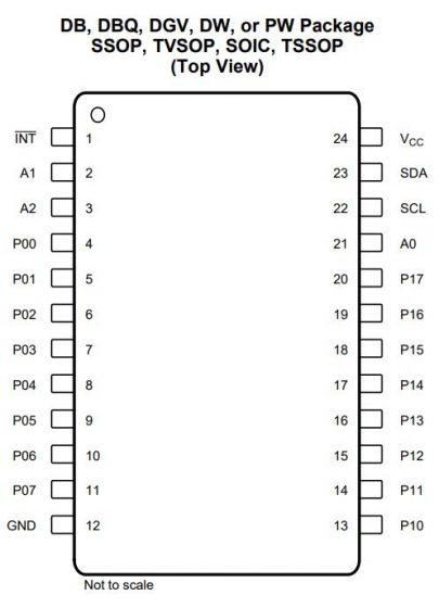
Set datasheet pins names instead a sequential one (Update 27/06/2021)
As you can see in the pinout of IC P0 is P00, P1 is P01 .. P7 is P07 and then there is no P8 and P9, insted 8th pin is P10, 9th pin is P11, etc…, so I add a define to change the management like so instead of sequential one.
// Define to manage original pinout of pcf8575
// like datasheet but not sequential
// #define NOT_SEQUENTIAL_PINOUT
Here the pins label.
#ifdef NOT_SEQUENTIAL_PINOUT
	#define P00  	0
	#define P01  	1
	#define P02  	2
	#define P03  	3
	#define P04  	4
	#define P05  	5
	#define P06  	6
	#define P07  	7
	#define P10  	8
	#define P11  	9
	#define P12  	10
	#define P13  	11
	#define P14  	12
	#define P15  	13
	#define P16  	14
	#define P17  	15
#else
	#define P0  	0
	#define P1  	1
	#define P2  	2
	#define P3  	3
	#define P4  	4
	#define P5  	5
	#define P6  	6
	#define P7  	7
	#define P8  	8
	#define P9  	9
	#define P10  	10
	#define P11  	11
	#define P12  	12
	#define P13  	13
	#define P14  	14
	#define P15  	15
#endif
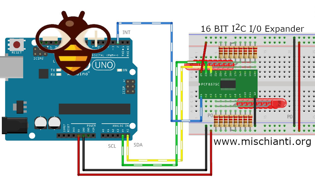
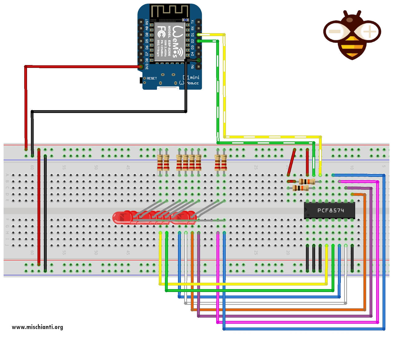
Connections schema
For the examples I use this wire schema on breadboard:
Additional examples from pcf8574 reusable on pcf8575
In the time peoples help me to create new examples, I’m going to add they here:
Wemos LEDs blink
From japan nopnop create an example to blink 8 leds sequentially.
/*
 * PCF8575 GPIO Port Expand
 * http://nopnop2002.webcrow.jp/WeMos/WeMos-25.html
 *
 * PCF8575    ----- WeMos
 * A0         ----- GRD
 * A1         ----- GRD
 * A2         ----- GRD
 * VSS        ----- GRD
 * VDD        ----- 5V/3.3V
 * SDA        ----- GPIO_4(PullUp)
 * SCL        ----- GPIO_5(PullUp)
 *
 * P0     ----------------- LED0
 * P1     ----------------- LED1
 * P2     ----------------- LED2
 * P3     ----------------- LED3
 * P4     ----------------- LED4
 * P5     ----------------- LED5
 * P6     ----------------- LED6
 * P7     ----------------- LED7
 *
 */

#include "Arduino.h"
#include "PCF8575.h"  // https://github.com/xreef/PCF8575_library

// Set i2c address
PCF8575 pcf8575(0x20);

void setup()
{
  Serial.begin(9600);

  // Set pinMode to OUTPUT
  for(int i=0;i<8;i++) {
    pcf8575.pinMode(i, OUTPUT);
  }
  pcf8575.begin();
}

void loop()
{
  static int pin = 0;
  pcf8575.digitalWrite(pin, HIGH);
  delay(1000);
  pcf8575.digitalWrite(pin, LOW);
  delay(1000);
  pin++;
  if (pin > 7) pin = 0;
}
Wemod LEDs blink inverted
Here a new version of leds blink that simply I put positive of the led on VCC and negative on pcf8575, so the power is provided by VCC.
/*
 * PCF8575 GPIO Port Expand
 * Inverted led test: all led is connected with anodo to the IC
 *
 * PCF8575    ----- WeMos
 * A0         ----- GRD
 * A1         ----- GRD
 * A2         ----- GRD
 * VSS        ----- GRD
 * VDD        ----- 5V/3.3V
 * SDA        ----- GPIO_4(PullUp)
 * SCL        ----- GPIO_5(PullUp)
 *
 * P0     ----------------- LED0
 * P1     ----------------- LED1
 * P2     ----------------- LED2
 * P3     ----------------- LED3
 * P4     ----------------- LED4
 * P5     ----------------- LED5
 * P6     ----------------- LED6
 * P7     ----------------- LED7
 * P8     ----------------- LED8
 * P9     ----------------- LED9
 * P10     ----------------- LED10
 * P11     ----------------- LED11
 * P12     ----------------- LED12
 * P13     ----------------- LED13
 * P14     ----------------- LED14
 * P15     ----------------- LED15
 *
 */

#include "Arduino.h"
#include "PCF8575.h"  // https://github.com/xreef/PCF8575_library

// Set i2c address
PCF8575 pcf8575(0x20);

void setup()
{
  Serial.begin(9600);

  // Set pinMode to OUTPUT
  for(int i=0;i<16;i++) {
    pcf8575.pinMode(i, OUTPUT);
  }
  for(int i=0;i<16;i++) {
	  pcf8575.digitalWrite(i, HIGH);
  }

  pcf8575.begin();
}

void loop()
{
  static int pin = 0;
  pcf8575.digitalWrite(pin, LOW);
  delay(1000);
  pcf8575.digitalWrite(pin, HIGH);
  delay(1000);
  pin++;
  if (pin > 15) pin = 0;
}
Demostration video
Esp32 leds blink using secondary i2c channel.
Here I create a variant of example to show how to use secondary i2c channel of a esp32.
#include "Arduino.h"
/*
 * 	PCF8575 GPIO Port Expand
 *  Blink all led
 *  by Mischianti Renzo <https://mischianti.org>
 *
 *  https://mischianti.org/
 *
 *
 * PCF8575    ----- Esp32
 * A0         ----- GRD
 * A1         ----- GRD
 * A2         ----- GRD
 * VSS        ----- GRD
 * VDD        ----- 5V/3.3V
 * SDA        ----- 21
 * SCL        ----- 22
 *
 * P0     ----------------- LED0
 * P1     ----------------- LED1
 * P2     ----------------- LED2
 * P3     ----------------- LED3
 * P4     ----------------- LED4
 * P5     ----------------- LED5
 * P6     ----------------- LED6
 * P7     ----------------- LED7
 *
 */

#include "Arduino.h"
#include "PCF8575.h"  // https://github.com/xreef/PCF8575_library

// Instantiate Wire for generic use at 400kHz
TwoWire I2Cone = TwoWire(0);
// Instantiate Wire for generic use at 100kHz
TwoWire I2Ctwo = TwoWire(1);

// Set i2c address
PCF8575 pcf8575(&I2Ctwo, 0x20);
// PCF8575 pcf8575(&I2Ctwo, 0x20, 21, 22);
// PCF8575(TwoWire *pWire, uint8_t address, uint8_t interruptPin,  void (*interruptFunction)() );
// PCF8575(TwoWire *pWire, uint8_t address, uint8_t sda, uint8_t scl, uint8_t interruptPin,  void (*interruptFunction)());

void setup()
{
  Serial.begin(112560);

  I2Cone.begin(16,17,400000); // SDA pin 16, SCL pin 17, 400kHz frequency

  // Set pinMode to OUTPUT
  for(int i=0;i<8;i++) {
    pcf8575.pinMode(i, OUTPUT);
  }
  pcf8575.begin();
}

void loop()
{
  static int pin = 0;
  pcf8575.digitalWrite(pin, HIGH);
  delay(400);
  pcf8575.digitalWrite(pin, LOW);
  delay(400);
  pin++;
  if (pin > 7) pin = 0;
}


The OPEN-SMART PCF8575 module does not produce a logical unit, this will not work. https://youtu.be/k4ZHBQkomos
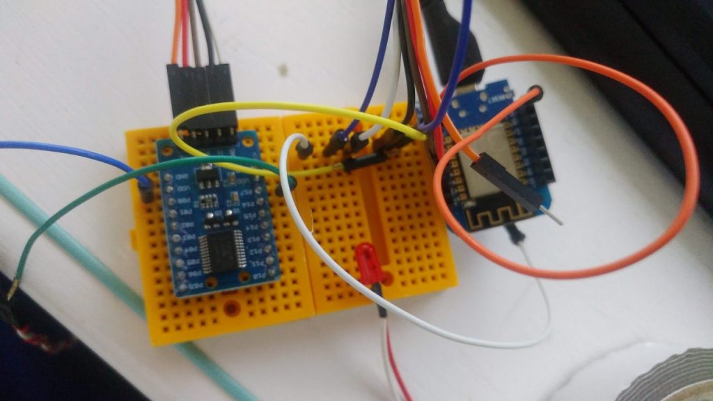
Hi,
I use the same module (http://s.click.aliexpress.com/e/cHDqUPkk) and I tested the library with this.
Please can you send the code and the connection schema.
First test you can try is to use an i2c scanner https://playground.arduino.cc/Main/I2cScanner/ and send the response.
Bye tell me the result.
The modules work for me, but not correctly, I can’t get 3.3 Volts on the GPIO outputs (logical unit). A logical zero works correctly and GPIO 10-17 does not work at all.
Hi khvalera,
I restore the breadboard and retest the library, It’s work correctly, here the video of the test to check all the output
https://youtu.be/jWeHzBLeN6s
if you send the sketch and the connection schema we try to find a solution for you.
Bye Renzo
in your drawings PCF8574
Yes, as I write I create a library that can reuse the pcf8574 examples, so I post the pcf8574 examples adapted for pcf8575 with schema for reference.
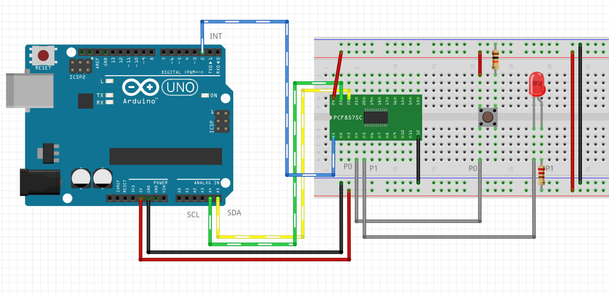
Where is A0 in the board ?
Ho Aican,
in the first board you can’t set A0 pin, only in the second you can
Bye Renzo
OK, I supposed…But I wasn´t sure. I suggest you to put a photo of the second one and a warning for clarity reasons. Thanks
Can you give an example of connecting matrix keyboard with interrupt?
I made a mistake when I tried.Because of my stupidity.
I used google translate,If you have any offence,please forgive me.
Thanks!
Hi Ruxia,
I try to do a connection schema, but please open a Topic on Forum here
http://mischianti.org/forums/forum/yours-project/
Bye Renzo
Fine libruary. Can you add non-blocking function for debounce, double click and holding on inputs?
Hi John,
I think in the future can be a possible development. But I have a lot of idea and few time.
Bye Renzo
Hi Mr.Renzo,
I need your help using PCF8575 with esp32. My project want to use PCF8575 to read 45 IR sensor, i already follow your tutorial and succeed using button as in input, but for IR sensor i have no idea how to impliment
Hi Felanino,
we need more space to write, open a topic in the relative section and we try to help you.
Bye Renzo
Hi Renzo,
How do you control each individual pins? for example, turn on P15 only. thanks
Hi K,
here you are
if you want read a single input:
If you want write a digital value you must do:
or:
Bye Renzo
Hi, I would like to use this PCF8575 for a 4×4 matrix keyboard, but I’ve been testing libraries for 5 days and I can’t, can you put together an example for me?
Hi Matheus,
open a forum topic and post your code. We can check It and see if we can help you.
Bye Renzo
begin() should have an overload to provide the address as well. There are a few cases when it is not possible or advised during the declaration. I made this change by simply adding:
//PCF8575.h
void begin(uint8_t address);
//PCF8575.cpp
void PCF8575::begin(uint8_t address){
_address = address;
PCF8575::begin();
}
I undrestand that for simple Arduino sketches this is not am issue. But for properly formed Arduino C++ projects under platform IO, this is very nice to have.
Hi Mikeys,
thanks for the suggestion I’m going to release It in the next version.
Bye Renzo
hi,
can you explain me how to change the i2c adress of the module ? i know it is with pin a0 a1 a2 but i dont rly understand HOW to do it
have a nice day
shaz
Hi Shaz,
you can find the detail of constructor, where you must set the address, in this section.
You can find some examples in the examples library folder, like this basic one.
Bye Renzo
Hi, looks like your library has problem with combining read and write mode:
writeByteBuffered = writeByteBuffered & writeMode;
_wire->write((uint8_t) writeByteBuffered);
_wire->write((uint8_t) (writeByteBuffered >> 8));
so if that pin in input mode you force value 0 into that bit. So any digitalWrite() ruins all inputs (sets them to 0 ).
Hi Vyacheslav,
If I remember, the pcf8575 needs to be set to 0 to use the pin in input mode.
Bye Renzo
Unfortunately, you are wrong:
The device features a 16-bit quasi-bidirectional
input/output (I/O) port (P07–P00, P17–P10), including
latched outputs with high-current drive capability for
directly driving LEDs. Each quasi-bidirectional I/O can
be used as an input or output without the use of a
data-direction control signal.
So basically there is no input output direction. If there is 1 on output then you can pull it down externally, as it is driven by a resistor, But when it is 0 on output you cannot drive it high as it pulled by a transistor,
Hi Vyacheslav,
I check this thing some time ago because there was a problem in some situation.
Bye Renzo
That description in middle is for PDF document for pcf8575 and as described there is no “INPUT MODE” for pins, they are quasi directional. I confirmed that on actual hardware – as soon as I output anything to a single output bit all inputs flip to zero and become unusable. I had to switch to alternative library that does not write zeros – works as expected for inputs and outputs. So currently your library is unusable for using pcf8575 for input and output at the same time.
Indeed, the library is not designed to handle a pin as both input and output simultaneously. I’ve never encountered a need to implement such functionality.
Bye Renzo