
How to reuse 4 and 6 wires stepper motors for your projects
Stepper motors are used in various types of equipment for accurate rotation angle and speed control using pulse signals. Stepper motors generate high torque with a compact body, and are ideal for quick acceleration and response. Stepper motors also hold their position at stop, due to their mechanical design. Stepper motor solutions consist of a driver (takes pulse signals in and converts them to motor motion) and a stepper motor.
When you start to create a CNC or something similar you need a stepper motor, probably you can find they inside your trash.
If you have and old printer or better a laser printer, probably you can get 2 Nema17 motor. I specify old because newest one use a brushless motor with feedback.
But the real problem when you decide to reuse stepepr, is the identification of the coil.
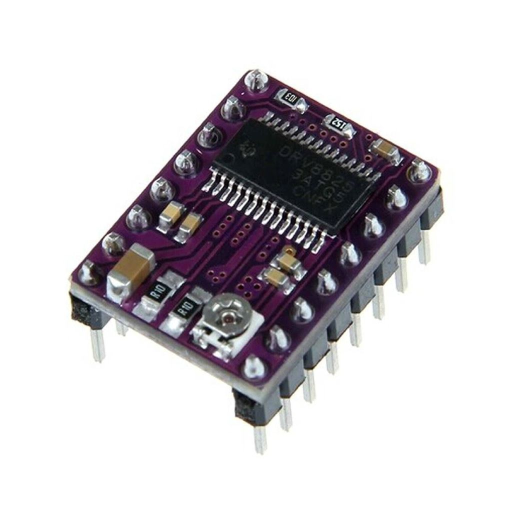
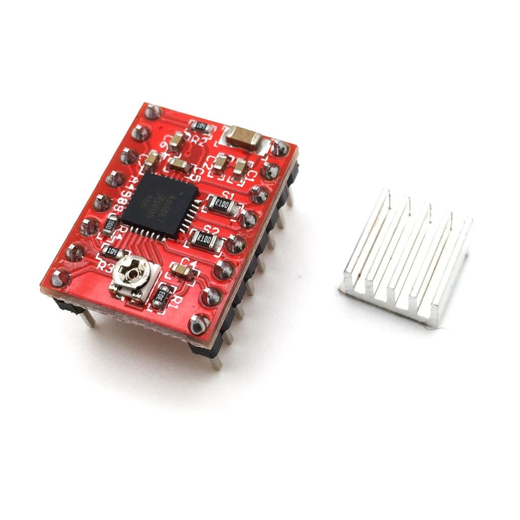
To use It the best solution is to use a driver, the most common one is A4988, but existing various models.
4 wires stepper motors
The most common motors is 4 wires (bipolar) and 6 wires motors.
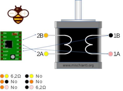
To use this motor you must identify the coil, take your tester and start check de restitance of all coils.
As you can clearly see from the images and the video for the bipolar motors it is simply necessary to find the connected ones, in practice the pairs will be formed by the wires that have a resistance different from 0.
6 wires stepper motors
This type of motor is more complex to use but with a tester and some patience you can find the 4 wires you need to connect.
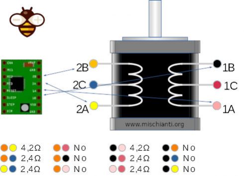
As you can see in this case the pairs of wires that must be taken are those that have a greater resistance, ie those more external to the coils.
When you don’t have the specifications
Normally, the motors that you find inside the printers are not easily traceable consequently, you are without specifications.
Given that the circular stepper motors (not nema17) usually have 75 steps and not 200 like the classic nema17 (there is also the 400 variant), the real problem is how much voltage and current are given to the motors.
Amperage drivers
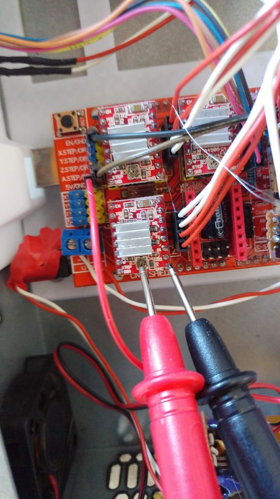
There is a simple “trick/way” to set the correct amperage. You must put tester + on the potentiometer and tester – to GND of the driver (look at the image) then:
- DRV8825: Imax = 2 * Vref (if Imax = 1.5A, then Vref is to be set to 1.5/2 V = 0.75V)
- A4988: Imax = 2,5 * Vref
In my situation, I put 0,8v*2,5 = 2A even if the step amp phase is 1,7amp but I need more power.
Step to follow to set the right input
I recommend following the following steps:
- Trivially test the outputs of the power supply to determine the rating.
If you can’t do this, follow the steps below:
- Start with 12v and set the maximum amperage per phase on the driver (for the A4988 2A): the low voltage affects the speed of rotation and naturally forces you to a greater amperage with a consequent increase in temperature. The motors you extract usually have 24-36v but they also work at 12v.
- If the temperature as we expect it becomes too high, decrease the amperage to obtain a high but acceptable temperature.
- If you get a very high temperature, increase the voltage and repeat the steps above.
Test the motors
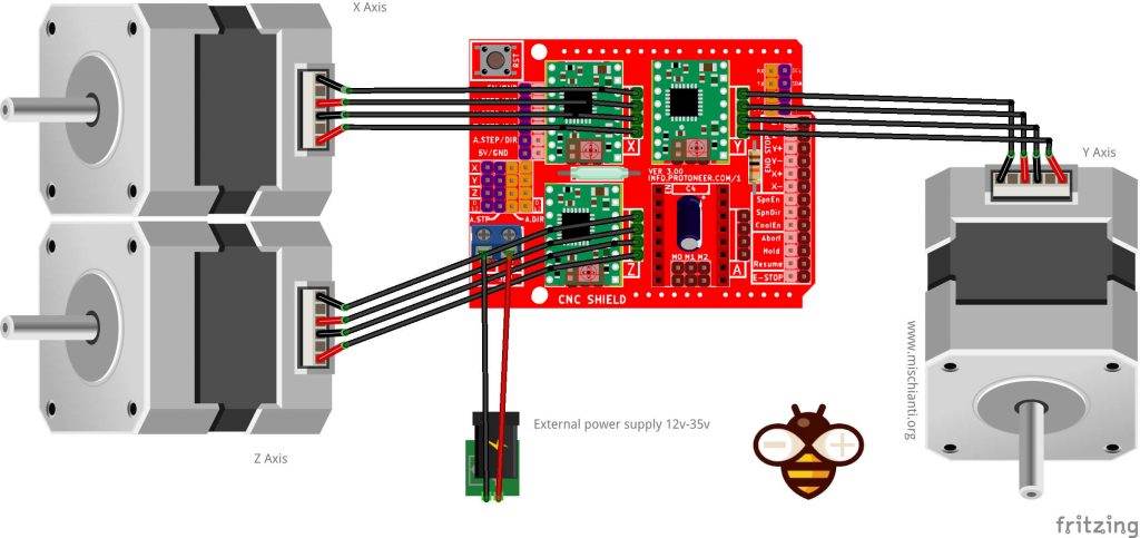
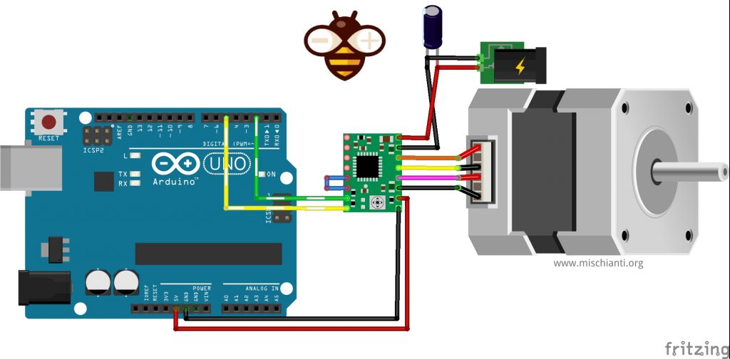
I create a silly program to check the motor, normally I connect them on CNC Shield, but if you don’t have It you can directly connect to a driver.
I also use that program to calculate the exact number of steps/mm when setting the parameters of my CNCs.
Some Arduino have problem when you are doing a long-running transmission with grbl firmware; pay attention.
You can find here Arduino UNO - Arduino MEGA 2560 R3 - Arduino Nano - Arduino Pro Mini
You can find here AliExpress
You can get the code from my GitHub, here you can find the repository.
Thanks
This article is an integration for the series of Cyclon PCB Factory, take a look.


Dear Renzo: You did not say a word about 8 wires motors? The idea is to convert them to 4 wire motors but the problem is which wires to connect together, and how? As we saw stepping motors have 4 coils inside and the first step is to identify the pairs of wires which connect to these 4 coils. This is very easily done with a DVM. Now comes a long description but actually very simple. (Some methods use a stepper motor driver and test by trial & error, others use an oscilloscope, but we will only need a DVM). How are we going to do this:
A make stepper motor turn by driving current into its coils in a certain sequence. However when we cause it’s axle to spin even slightly by hand the moving magnet core of the motor induces measurable AC voltage in the coils. Well, the induced voltages have different phase relations with each other but for each coil there exists one other coil which has practically the same voltage magnitude but in-phase or reversed-phase, depending in the connection. Connecting two coils in series and measuring AC voltage between the edges will always cause some reading, except one combination: When the identical coils are connected in reverse phase- the voltage in one of them will counter-act the second voltage and the reading will be practically zero. CAREFUL: All the coils are also capacitively coupled and the DVM (which has a high internal resistance) might show a reading. This capacitive coupling must be neutralised by connecting a resistor of about 10K in parallel with the DVM.
The second step now is to call any of the coils No.1 (let’s say it is the coil connected to the green and pink wires) and then we can also decide about the polarity and call the pink wire the (1+), so the green one is of course (1-). Next step is to connect one of these wires (say the 1- wire ) to each of the other coils – once to one wire and then to the other, and the same time connect the DVM between the other edges. Repeat this until the DVM reading remains zero while the axle is spinned. In this case the correct coils are already connected in parallel on one edge. By removing the DVM from the open edges and shorting them together parallel connection is completed. The same is done with the remaining two coils.
At this point you can call the coil pairs 1A 1B and 2A 2B. All the (-) sides are now connected together in pairs, and so are the (+) sides. If series connection I trust you to make them like you would connect pairs of batteries in series.
Hi Hanan,
thank you for your valuable contribution, if I find some time I’m going to add your instruction on the article.
Thanks Renzo
Thanks for your sharing, this content is just i want to find.
Thanks to write, I’m happy to help you.
Bye Renzo
Hello. I have connected only one stepper motor to cnc shield, and it don’t run. What can be the problem?
I don’t know Vlad, if there isn’t noise I think It’s the power supply.
Bye Renzo