ESP-01 modules programming board
ESP-01 is low cost esp8266 module, with built-in WIFI.
It was created as Arduino WIFI module, but It’s more powerful than an Arduino, than now if you need a little module to control a relay or some simple digital datalogger It’s the best solution.
Specs
Here the esp esp01 - esp01 programmer
Exists some variant of this module, but all have a processor L106 32-bit RISC microprocessor core based on the Tensilica Xtensa Diamond Standard 106Micro running at 80 MHz, when you buy one of It you must pay attention only on Flash, some have 512 KiB Flash, other 1MiB
Pins
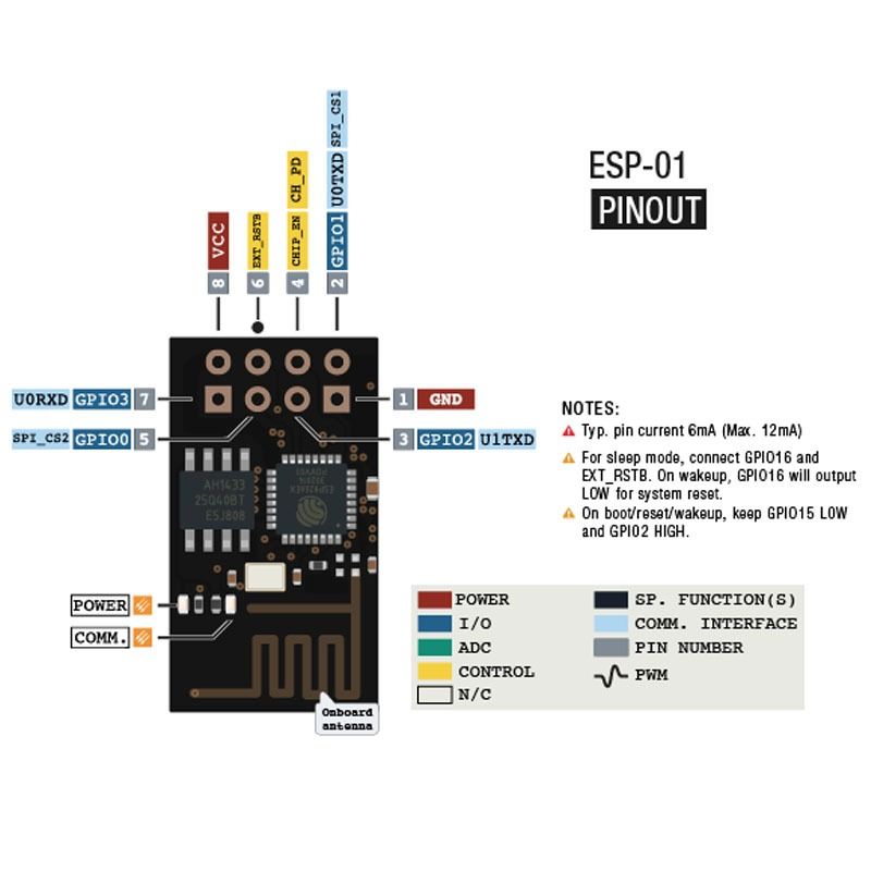
Pin Definition
| Name | Type | Function |
| VCC | P | Power 3.0 ~ 3.6V |
| GND | P | Ground |
| RESET | I | External reset signal (Low voltage level: Active) |
| CH_PD | I | Chip Enable. High: On, chip works properly; Low: Off, small current |
| GPIO0(FLASH) | I/O | General purpose IO, If low while reset/power on takes chip into serial programming mode |
| GPIO1(TX) | I/O | General purpose IO and Serial TXd |
| GPIO3(RX) | I/O | General purpose IO and Serial RXd |
| GPIO2 | I/O | General purpose IO and Serial1 TXd |
Note: TX1 and TX GPIO1 are internally connected, On board blue LED is also connected to this pin
As described for programming mode you must set to low GPIO0 and reset the module, than you can upload the sketch.
Programming
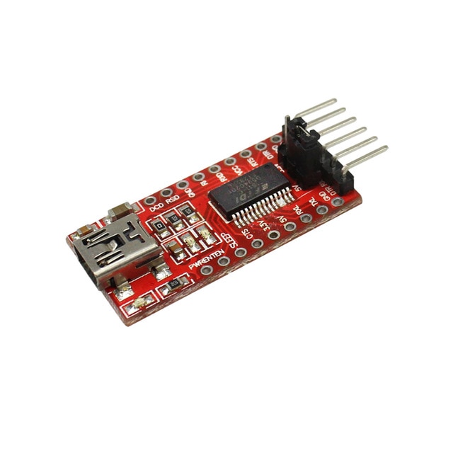
As you can see this module haven’t on board usb so the easiest way to program is to use a USB to TTL converter, you can find it at 1$.
I have some problem with more expensive FT232RL or FT232 module, instead a CH340G or CH340 working very good.
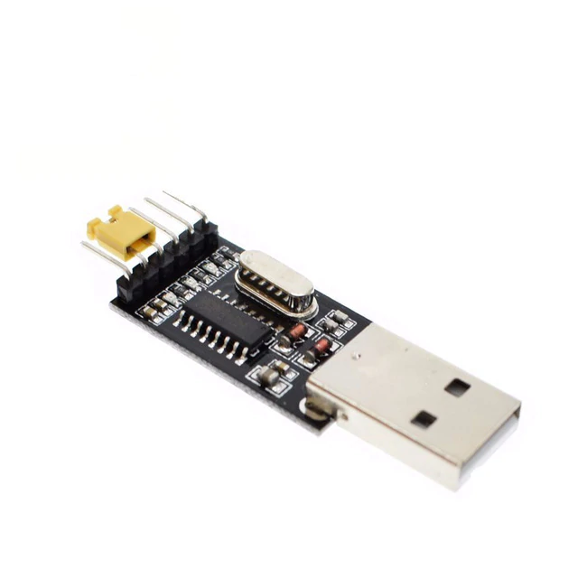
Here the adapter USB to TTL CH340G - USB to TTL FT232RL
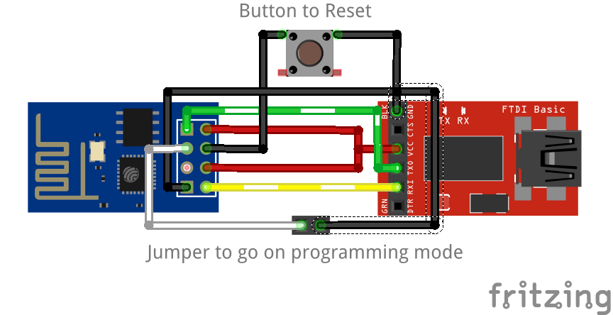
The base connection schema is quite simple, you must put 3.3v on VCC and CH_PD (to power and enable), then put on GND the GND and GPIO0 (the last to put module on programming mode), than connect RX to TX and TX to RX.
Configure your ide
Than you must configure your Arduino IDE
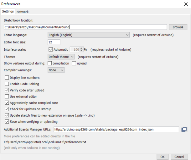
First you must add esp8266 url descriptor to your IDE
http://arduino.esp8266.com/stable/package_esp8266com_index.jsonGo to File –> Preferences and add the url on “Additional Boards Manager URLs”
Than you must add new board in Boards Manager
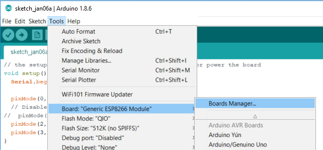
The boards to select is esp8266
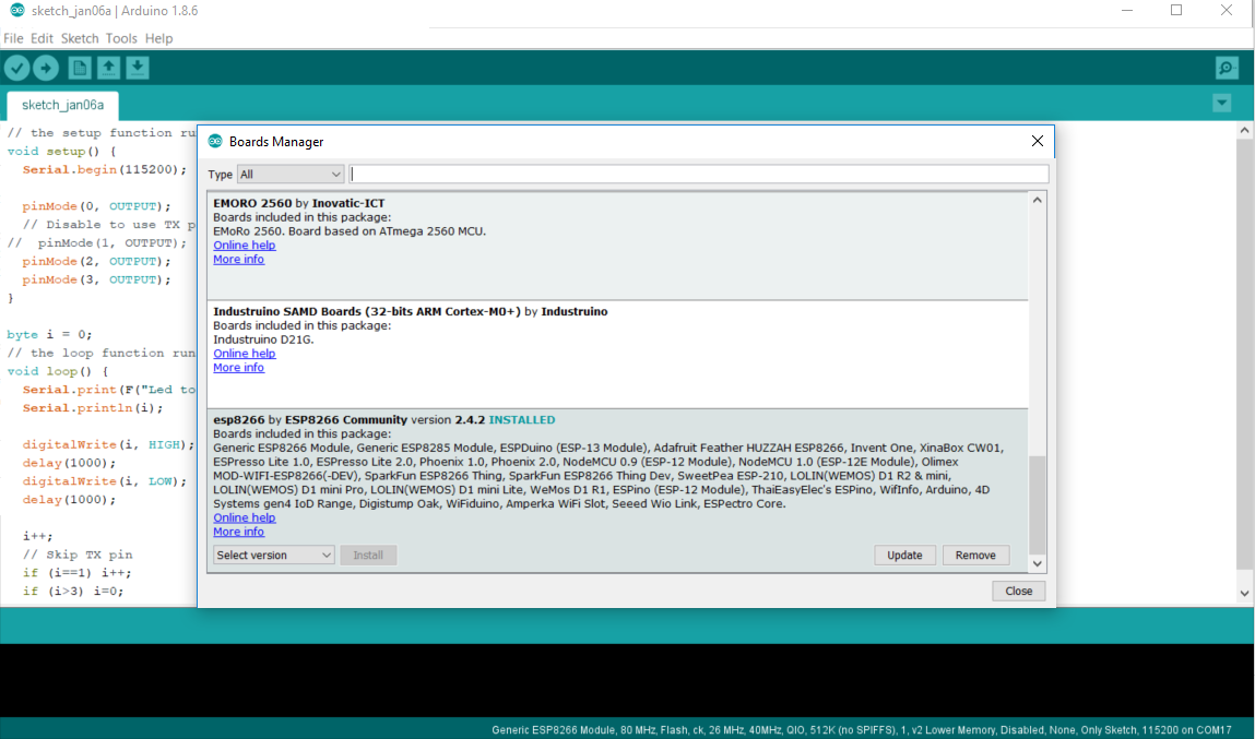
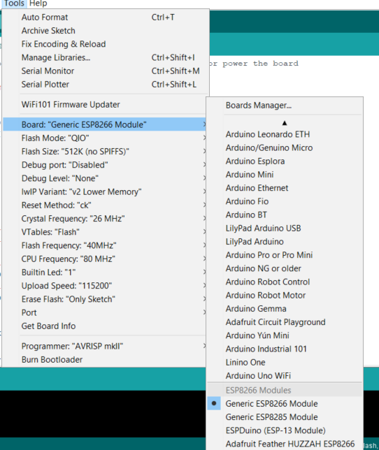
Now you can select generic esp8266 board from the list of board
Now you can upload your sketch.
Programming board
This process is tedious, you must connect then remove connection and so on, and to use all pins It’s very tedious.
My solution to this problem is to create a programming board (I’m fan of service board).
The functionality is:
- External power source to give more ampere to the circuit (esp01 pins have very low ampere);
- a switch to select programming mode and than release the GPIO0 pin;
- 2 switch to activate RX and TX and than to grant the use of that pin for the circuit;
- a reset button to start programming.
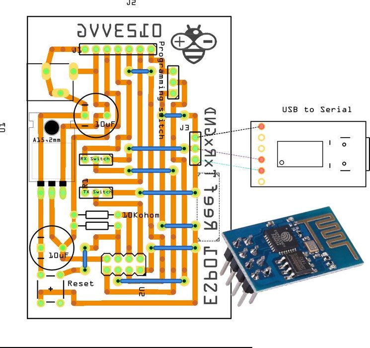
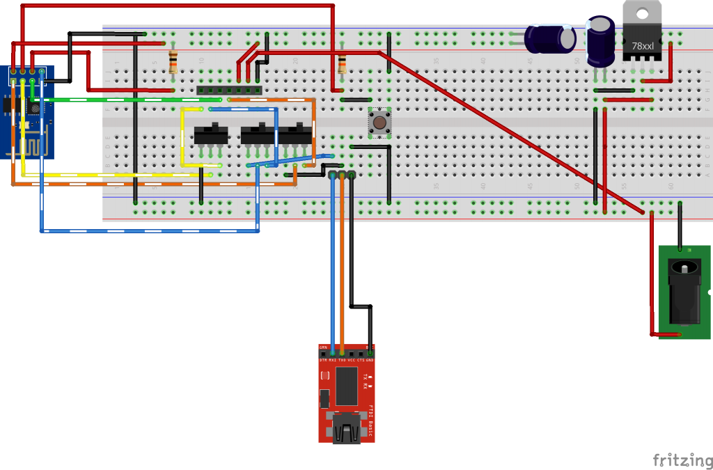
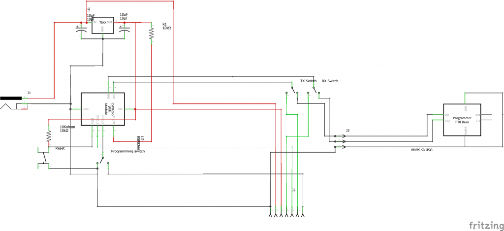
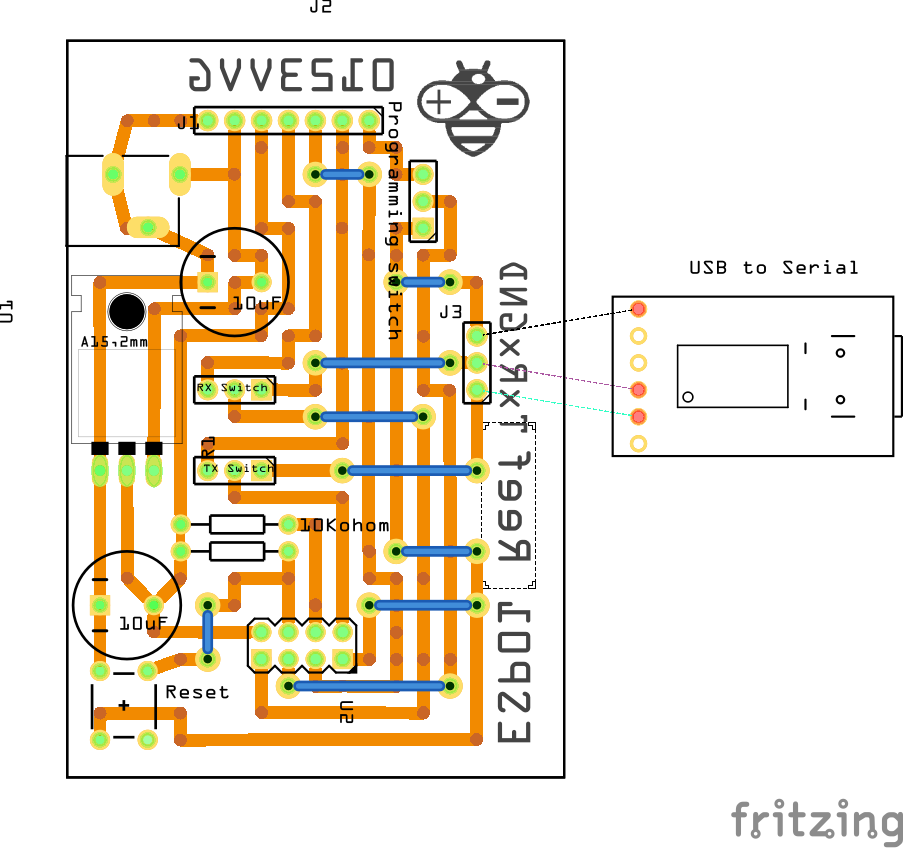
Here the breadboard, the schema and a prototype board:
PCB prototype
Order PCB for few Euro
You can find the esp01 programmer PCB here PCBWay

Milling PCB
I add the gcode file that I used with my CNC, so you can replicate my milling process.
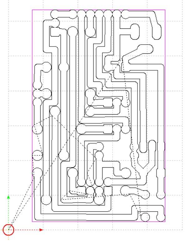
Gerber file
If you want reinterprete the board you can use the gerber file.
This file can be also used as data to send to service like PCBGoGo (http://www.pcbgogo.com/?code=y) that can create the board for you at very low cost.
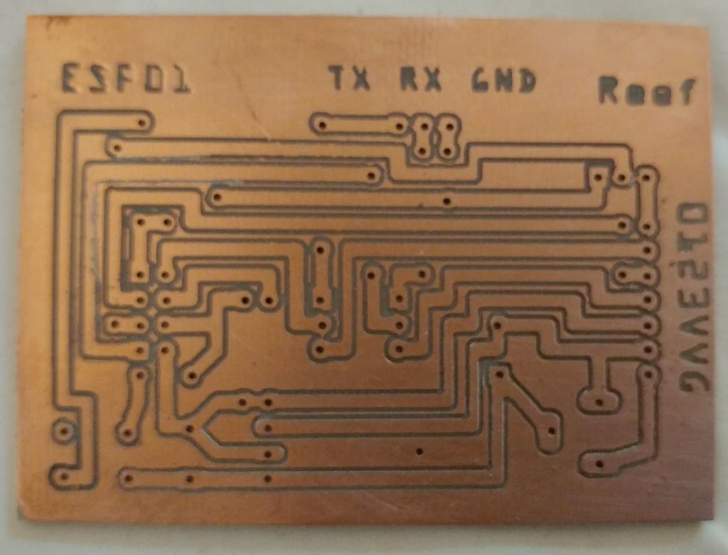
Etching
I don’t use this technique, but a lot of people prefer this type of creation.
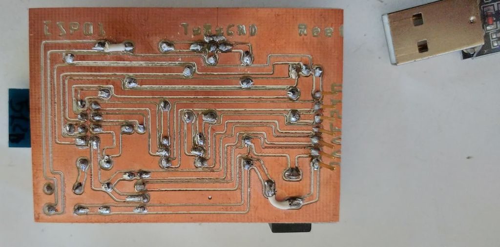
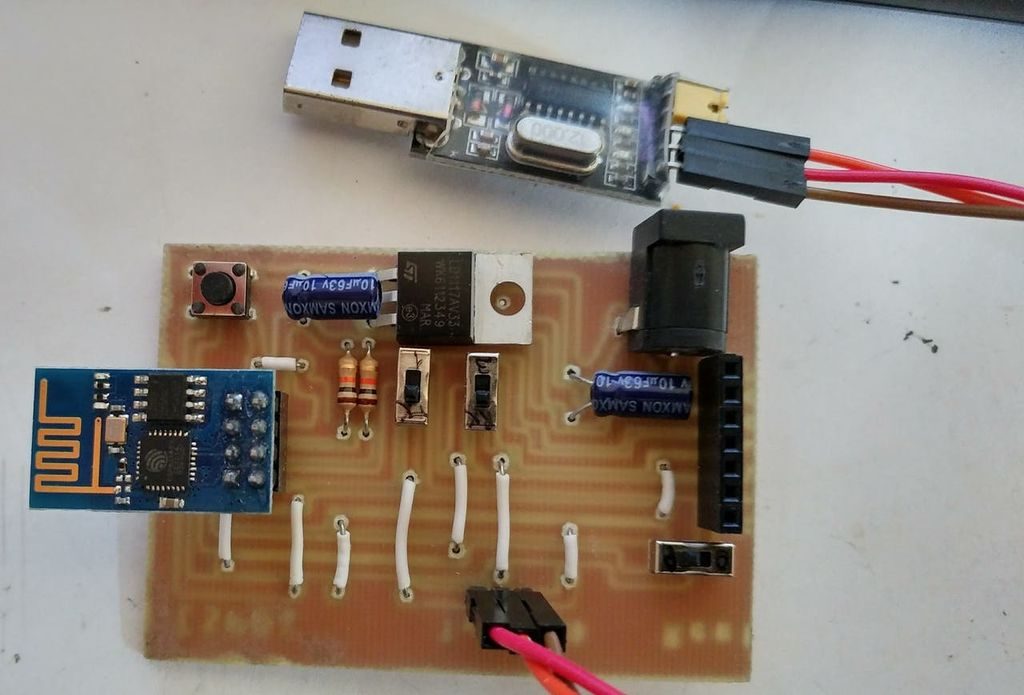
Result of milling process
I’d like to add the result of my old glorious router (created with an epson scanner and printer), quite rough but ok.
There is also a bug fixed by wire (in the file I give you is no more present).
Components
- 2 capacitor 10uF
- 2 resitor da 10Kohom
- a push button
- 3 SMD switch
- 1 LM1117T-3.3
- 1 barrel connector 5.5
PCB Assembly
Now start to assembly yhe board.
How to use the programming board
The usage is quite simple:
First insert esp01 in the board, than connect GND to GND, TX to RX and RX to TX of TTL to USB converter.
Now you are ready to program, I add some usage examples.
Upload a blink file
- In the board you must set the left switch in programming mode than click the resetbutton.
- Check that the switch of RX and TX It’s in trasfer mode.
- Than start upload the sketch.
- When finish put in “use mode” the board to put the programmer pin free, and the button to put TX in “use mode”.
- So you can check that external led blink because BUILTIN_LED is connected to TX pin.
Use all 4 pins of the board
- In the board you must set qith left switch in programming mode than click the resetbutton.
- Check that the switch of RX and TX It’s in trasfer mode.
- Than start upload the sketch.
- When finish put in “use mode” the board to put the programmer pin free, and the button to put RX and TX pins in “use mode”.
- So you use all 4 pin to control the led.
Use 3 pins to control led and one to serial debug
- In the board you must set the left switch in programming mode than click the resetbutton.
- Check that the switch of RX and TX It’s in trasfer mode.
- Than start upload the sketch.
- Connect the serial monitor to the correct port.
- When finish put in “use mode” the board to put the programmer pin free, and the button to put RX in “use mode”.
- So you use 3 pins to control the led and TX to debug the program.
Thanks
If you have problem or other write comment or open topic to the forum.